
With the DS18B20 temperature sensors in place, it was time to add the ‘depth’ part of the standard CDT suite. After reading an introduction to the Fundamentals of Pressure Sensor Technology, I understood that most of the pressure sensors out there would not be suitable for depth sensing because they are gauge pressure sensors, which need to have a “low side” port vented to atmosphere (even if the port for this is hidden from view).

This is one of our earliest pressure loggers with a 3″ pvc housing. We now use 2″ PVC pipes (shown at the end of this post) which are much easier to to construct. For an exploded view of the new housing see the appendix at the end of the article in Sensors.
I needed an “absolute” pressure transducer, that has had it’s low side port sealed to a vacuum. I found a plethora of great altimiter projects in the rocketry & octocopter world, (with Kalman filtering!) but far fewer people doing underwater implementations in caves. But there are a few DIY dive computer projects out there, at various stages of completion, that use versions of the MS5541C & MS5803 pressure sensors from Measurement Specialties, or the MPX5700 series from Freescale. Victor Konshin had published some code support for the MS5803 sensors on Github, but his .cpp was accessing them in SPI mode, and I really wanted to stick with an I2C implementation as part of my quest for a system with truly interchangeable sensors. That lead me to the Open ROV project were they had integrated the 14 bar version of the MS5803 into their IMU sensor package. And they were using an I2C implementation. Excellent! I ordered a couple of 2 bar, and 5 bar sensors from Servoflo ($25 each +shipping..ouch!) , and a set of SMT breakout boards from Adafruit. A little bit of kitchen skillet reflow, and things were progressing well. (note: I mount these sensors now by hand, which is faster after you get the hang of it it)

My first “real” hack on the project so far. (Note: This material was posted in early 2014 , and the only reason I did this hack was that at the time I was running the Tinyduino stack directly from an unregulated 4.5 battery. On my more recent loggers, built with regulated 3.3v promini style boards, I can just use the Vcc line to power the MS5803 sensors, without all this bother…)
But as I dug further into the MS5803 spec sheets I discovered a slight complication. These sensors required a supply voltage between 1.8 – 3.6 V, and my unregulated Tinyduino stack, running on 3 AA’s, was swinging from 4.7 down to 2.8v. I was going to need some sort of voltage regulator to bring the logic levels into a range that the senor’s could tolerate, with all the attendant power losses that implied… And then it dawned on me that this same problem must exist for the other I2c sensors already available on the Tinyduino platform. So perhaps I might be able to hack into those board connections and drive my pressure sensor? (instead of burning away months worth of power regulating the entire system) The Tiny Ambient Light Sensor shield carried the TAOS TSL2572 which had nearly identical voltage and power requirements to my MS5803.

I used JB weld to provide support for those delicate solder connections.
So their voltage regulator, and level shifter, could do all the work for me if I could lift those traces. But that was going to be the most delicate soldering work I have ever attempted. And I won’t pull your leg, it was grim, very grim indeed. Excess heat from the iron conducted across the board and melted the previous joints with each additional wire I added. So while the sensors themselves came off easily with an drywall knife, it took two hours (of colorful language…) to lift the traces out to separate jumper wires. I immediately slapped on a generous amount of JB weld, because the connections were so incredibly fragile. I produced a couple of these breakouts, because I have other sensors to test, and I face this same logic level/voltage problem on the I2C lines every time I power the unregulated Tiny duino’s from a computer USB port.
With a connection to the mcu sorted, it was time to look at the pressure sensor itself. Because I wanted the sensor potted as cleanly as possible, I put the resistor, capacitor, and connections below the breakout board when I translated the suggested connection pattern from the datasheets to this diagram:

This is viewed from above, with only one jumper above the plane of the SOIC-8 breakout. I used a 100nF (104) decoupling cap. The PS pin (protocol select) jumps to VDD setting I2C mode, and a 10K pulls CSB high, to set the address to 0x76. Connecting CSB to GND would set the I2C address to 0x77 so you can potentially connect two MS5803 pressure sensors to the same bus.
And fortunately the solder connections are the same for the 5 bar, and the 2 bar versions:

I’ve learned not waste time making the solder joints “look pretty”. If they work, I just leave them.
After testing that the sensors were actually working, I potted them into the housings using JB plastic weld putty, and Loctite E30CL:

The Loctite applicator gun is expensive, but it gives you the ability to bring the epoxy right to the edge of the metal ring on the pressure sensor.
So that left only the script. The clearly written code by by Walt Holm (on the Open ROV github) was designed around the 14 bar sensor; great for a DIY submersible, but not quite sensitive enough to detecting how a rainfall event affects an aquifer. So I spent some time modifying their calculations to match those on the 2 Bar MS5803-02 datasheet :
// Calculate the actual Temperature (first-order computation)
TempDifference = (float)(AdcTemperature – ((long)CalConstant[5] * pow(2, 8)));
Temperature = (TempDifference * (float)CalConstant[6])/ pow(2, 23);
Temperature = Temperature + 2000; // temp in hundredths of a degree C
// Calculate the second-order offsets
if (Temperature < 2000.0) // Is temperature below or above 20.00 deg C?
{T2 = 3 * pow(TempDifference, 2) / pow(2, 31);
Off2 = 61 * pow((Temperature – 2000.0), 2);
Off2 = Off2 / pow(2, 4);
Sens2 = 2 * pow((Temperature – 2000.0), 2);}
else
{T2 = 0;
Off2 = 0;
Sens2 = 0;}
// Calculate the pressure parameters for 2 bar sensor
Offset = (float)CalConstant[2] * pow(2,17);
Offset = Offset + ((float)CalConstant[4] * TempDifference / pow(2, 6));
Sensitivity = (float)CalConstant[1] * pow(2, 16);
Sensitivity = Sensitivity + ((float)CalConstant[3] * TempDifference / pow(2, 7));
// Add second-order corrections
Offset = Offset – Off2;
Sensitivity = Sensitivity – Sens2;
// Calculate absolute pressure in bars
Pressure = (float)AdcPressure * Sensitivity / pow(2, 21);
Pressure = Pressure – Offset;
Pressure = Pressure / pow(2, 15);
Pressure = Pressure / 100; // Set output to millibars
The nice thing about this sensor is that it also delivers a high resolution temperature signal, so my stationary pressure logger does not need a second sensor for that.

A Reefnet Census Ultra is co-deployed with my pressure sensor to ground truth this initial run.
So that’s it, the unit went under water on March 22, 2014, and the current plan is to leave it there for about 4 months. This kind of long duration submersion is probably way out of spec for the epoxy, and for the pressure sensors flexible gel cap. But at least we potted the sensor board with a clear epoxy, so it should be relatively easy to see how well everything stands up to the constant exposure. (I do wonder if I should have put a layer of silicone over top of the sensor like some of the dive computer manufacturers)
Addendum 2014-03-30
I keep finding rumors of a really cheap “uncompensated” pressure sensor out there on the net for about 5 bucks: the HopeRF HSF700-TQ. But I have yet to find any for sale in quantities less than 1000 units. If anyone finds a source for a small number of these guys, please post a link in the comments, and I will test them out. The ten dollar MS5805-02BA might also be pressed into service for shallow deployments using its extended range, if one can seal the open port well enough with silicone. And if all of these fail due to the long duration of exposure, I will go up market to industrial sensors isolated in silicon oil , like the 86bsd, but I am sure they will cost an arm and a leg.
Addendum 2014-04-15
Looks like Luke Miller has found the the float values used in the calculations from the ROV code generates significant errors. He has corrected them to integers and posted code on his github. Unfortunately one of the glitches he found was at 22.5°C, right around the temperature of the water my units are deployed in. I won’t know for some months how this affects my prototypes. With my so many sensors hanging off of my units, I don’t actually have enough free ram left for his “long int” calculations, so I am just logging the raw data for processing later.
Addendum 2014-09-10
The unit in the picture above survived till we replaced that sensor with a 5-Bar unit on Aug 25th. That’s five months under water for a sensor that is only rated in the spec sheets for a couple of hours of submersion. I still have to pull the barometric signal out of the combined” readings, but on first bounce, the data looks good (mirroring the record from the Reefnet Sensus Ultra) Since the 2-Bar sensor was still running, it was redeployed in Rio Secreto Cave (above the water table) on 2014-09-03. It will be interesting to see just how long one of these little sensors will last.
Addendum 2014-12-18
The 2Bar unit (in the photo above) delivered several months of beautiful barometric data from it’s “dry” cave deployment, and was redeployed for a second underwater stint in Dec 2014. The 5Bar unit survived 4 months of salt water exposure, but we only got a month of data from it because an epoxy failure on the temperature sensor drained the batteries instantly. After a makeshift repair in the field, it has now been re-deployed as a surface pressure unit. The good news is that we had the 5Bar sensor under a layer of QSil 216 Clear Liquid Silicone, and the pressure readings look normal compared to the naked 2bar sensor it replaced. So this will become part of my standard treatment for underwater pressure sensors to give them an extra layer of protection.
[NOTE: DO NOT COAT YOUR SENSORS LIKE THIS! – this silicone rubber coating failed dramatically later – it was only the stable thermal environment of the caves that made it seem like it was working initially and the silicone also seemed to change its physical volume with long exposure to salt water. I’m leaving the original material in place on this blog as it’s an honest record of the kinds of mistakes I worked through during this projects development.]
Addendum 2015-01-16
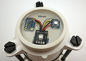
I know the MCP9808 is a little redundant here, but at $5 each, it’s nice to reach ±0.25ºC accuracy. The MS5803’s are only rated to ±2.5ºC, and you can really see that in the data when you compare the two. The low profile 5050 LED still has good visibility with a 50K Ω limiter on the common ground line. Test your sensors & led well before you pour the epoxy! (Note: the 9808 temp sensor & LED pictured here failed after about 8 months at 10m. I suspect this was due to the epoxy flexing under pressure at depth because of the large exposed surface area. The MS5803 was still working fine.)
Just thought I would post an update on how I am mounting the current crop of pressure sensors. My new underwater housing design had less surface area so I combined the pressure sensor, the temperature sensor, and the indicator LED into a single well which gives me the flexibility to use larger breakout boards. That’s allot of surface area to expose at depth, so I expect there will some flexing forces. At this point I have enough confidence in the Loctite ECL30 to pot everything together, even though my open ocean tests have seen significant yellowing. The bio-fouling is pretty intense out there, so it could just be critters chewing on the epoxy compound. Hopefully a surface layer of Qsil will protect this new batch from that fate.
Addendum 2015-03-02
Just put a 4-5mm coating of Qsil over a few MS5803’s in this new single-ring mount, and on the bench the coating seems to reduce the pressure reading by between 10-50 mbar, as compared to the readings I get from the sensors that are uncoated. Given that these sensors are ±2.5% to begin with, the worst ones have about doubled their error. I don’t know if this will be constant through the depth range, or if the offset will change with temperature, but if it means that I can rely on the sensor operating for one full year under water, I will live with it.
Addendum 2015-04-06 : Qsil Silicone Coating idea FAILS
Just returned from a bit of fieldwork where we had re-purposed a pressure sensor from underwater work to the surface. That sensor had Qsil silicone on it, and while it delivered a beautiful record in the the flooded caves, where temperatures vary by less than a degree, it went completely bananas out in the tropical sun where temps varied by 20°C or more per day. I suspect that the silicone was expanding and contracting with temperature, and this caused physical pressure on the sensor that completely swamped the barometric pressure signal.
Addendum 2016-02-01

Use the smallest with zip tie you can find.
Since these are SMD sensors, mounting them can be a bit of a pain so I though would add a few comments about getting them ready. I find that holding the sensor in place with a zip tie around the SOIC-8 breakout makes a huge difference. Also, I find it easier to use the standard sharp tip on my Hakko, rather than a fine point which never seem to transfer the heat as well.

I also use a wood block to steady my hand during the smd scale soldering.
I plant the point of the iron into the small vertical grooves on the side of the sensor. I then apply a tiny bead of solder to the tip of the iron, which usually ends up sitting on top, then I roll the iron between my fingers to bring this the bead around to make contact with the pads on the board. So far this technique has been working fairly well, and though the sensors do get pretty warm they have all survived so far. If you get bridging, you can usually flick away the excess solder if you hold the sensor so that the bridged pads are pointing downwards when you re-heat them.

After mounting the sensor to the breakout board, I think of the rest of the job in two stages: step one is the innermost pair (which are flipped horizontally relative to each other) , and step two by the outermost pair where I attach the incoming I2C wires. Here SCL is yellow, and SDA is white. In this configuration CSB is pulled up by that resistor, giving you an I2C address of 0x76. If you wanted a 0x77 buss address, you would leave out the resistor and attach the now empty hole immediately beside the black wire to that GND line.
Sometimes you need to heat all of the contacts on the side of the sensor at the same time with the flat of the iron to re-flow any bridges that have occurred underneath the sensor itself. If your sensor does not work, or gives you the wrong I2C address, its probably because of this hidden bridging problem.

Adafruit still makes the nicest boards to work with, but the cheap eBay SOIC8 breakouts (like the one pictured above) have also worked fine and they let me mount the board in smaller epoxy wells. Leave the shared leg of the pullup resistor/capacitor long enough to jump over to Vcc on the top side of the board .
Addendum 2016-03-08
Have the next generation of pressure sensors running burn tests to see what offsets have been induced by contraction of the epoxy. I’ve been experimenting with different mounting styles, to see if that plays a part too:

The housings are left open during the bookshelf runs as it takes a couple of weeks for the pvc solvent to completely clear out, and who knows what effect that would have on the circuits. (Note: for more details on how I built these loggers and housings, you can download the paper from Sensors )
The MS5803’s auto-sleep brilliantly, so several of these loggers make it down to ~0.085 mA between readings, and most of that is due to the SD card. I’m still using E-30Cl, but wondering if other potting compounds might be better? There just isn’t much selection out there in if you can only buy small quantities. The E30 flexed enough on deeper deployments that the bowing eventually killed off the 5050 LEDs. ( standard 5mm encapsulated LEDs are a better choice ) And I saw some suspicious trends in the temp readings from the MCP9808 under that epoxy too…
Addendum 2016-03-09
Just a quick snapshot from the run test pictured above:

These are just quick first-order calculations (in a room above 20°C). Apparently no effect from the different mounting configurations, but by comparison to the local weather.gov records, the whole set is reading low by about 20 mbar. This agrees with the offsets I’ve seen in other MS5803 builds, but I am kicking myself now for not testing this set of sensors more thoroughly before I mounted them. Will do that properly on the next batch.
Addendum 2016-09-22

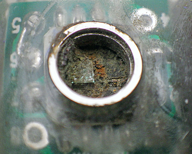
The inside of an MS5803, after the white silicone gel covering the sensor was knocked off by accident.
You can change the I2C address on these sensors to either 0x76 or 0x77 by connecting the CSB pin to either VDD or GND. This lets you connect two pressure sensors to the same logger, and I’ve been having great success putting that second sensor on cables as long as 25 m. This opens up a host of possibilities for environmental monitoring especially for things like tide-gauge applications, where the logger can be kept above water for easier servicing. It’s worth noting that on a couple of deployments, we’ve seen data loss because the senor spontaneously switched it’s bus address AFTER several months of running while potted in epoxy. My still unproven assumption is that somehow moisture penetrated the epoxy, and either oxidized a weak solder joint, or provided some other current path that caused the sensor to switch over.
Addendum 2017-04-30
Hypersaline environments will chew through the white cap in about 3 months.
Given what a pain these little sensors are to mount, it’s been interesting to see the price of these pressure sensor breakout modules falling over time. This spring the 1 & 14 bar versions fell below $24 on eBay. Of course they could be fake or defective in some way, but I’m probably going to order a few GY-MS5803’s to see how they compare to the real thing.
Addendum 2020-02-29: Mounting Pressure Sensors under Oil
When exposed to freshwater environments & deployed at less than 10m depth, a typical MS5803 gives us 2-3 years of data before it expires. However we often do deployments in ocean estuaries where wave energy & high salt concentrations shorten the operating life to a year or less. So now we mount them on replaceable dongles, so that it’s easy to replace an expired sensor in the field. I described that sensor mounting system in the 2017 build videos:
Media isolated pressure sensors are common in the industrial market, but they are quite expensive. So we’ve also used these dongles to protect our pressure sensors under a layer of oil. I’ve seen this done by the ROV crowd using comercial isolation membranes, or IV drip bags as flexible bladders, but like most of our approaches, the goal here was to develop a method I could retro-fit to the units already in the field, and repair using materials from the local grocery store:
 The sensor is already potted into a NIBCO 1/2″ x 3/4″ Male Pex Adapter, to which we will mate a NIBCO 3/4″ Female Swivel Adapter. |
 Since the balloon in this case is too large, I simply tie & cut it down to size. You can also cut your membrane from gloves or use small-size nitrile finger cots |
 Remove the O-ring from the swivel adapter stem and insert the ‘neck’ of the balloon. |
 Pull the balloon through till the knot-end becomes visible. |
 Pull the balloon over the rim on the other side of the pex adapter. |
 Place the O-ring over the balloon, and cut away the rolled end material. |
 Now the threaded swivel ring will not bind on rubber when it gets tightened. Note the knot is just visible at the stem |
 Fill the mounted sensor ‘cup’ with silicone oil or mineral oil. You could also use lubricants produced by o-ring manufacturers that do not degrade rubbers over time.
|
 Gently push the balloon back out of the stem so that there is extra material in direct contact with oil. You don’t want the membrane stretched tight when you bring the parts together. |
 Then place the swivel stem on the sensor cup with enough extra membrate so it can moves freely inside the protective stem. |
 . . . and tighten down with the threaded ring to create a water-tight seal.
|
 After assembly the membrane material should be quite loose to accommodate pressure changes & any thermal expansion of the oil. |
Small trapped air bubbles can cause serious problems in dynamic hydraulic systems, but I don’t think the volume of air in the balloon matters as much when you are only taking one reading every 5-15 minutes. If you do this oil mount with other common pressure sensors like the BMP280 then you are pretty much guaranteed to have some kind bubble inside the sensor can, but so far I have not seen any delta when compared to ‘naked’ sensors of the same type on parallel test runs. It’s also worth noting that depending on the brand, finger cots can be quite thin, and in those cases I sometimes use two layers for a more robust membrane. Put a drop or two of oil between the joined surfaces of the membranes with a cotton swab to prevent binding – they must slide freely against each other and inside the pex stem.

Yes, there is a pressure sensor buried in there! We got data for ~3.5 months before the worms covered it completely. In these conditions a larger IV bag is a better choice than the small oil reservoir I’ve described above. Simply attach that flexible oil-filled bladder directly to the stem of a 1/2″pex x 3/4″swivel connector with a crimp ring.
It’s also worth adding a comment here on the quality of the oil that you use. For example, silicone oil can be used on o-rings, and sources like Parker O-ring handbook describe this as “safe all rubber polymers”. But it’s often hard to find pure silicone oil and hardware store versions often use a carrier or thinner (like kerosene) that will damage or even outright dissolve rubbers on contact. And although we’ve used the mineral oil/balloon combination for short periods, nitrile is a better option in terms of longevity. With nitrile’s lower flexibility, you have to be careful when fitting cots over the o-ring end of the connector tube because it leaves leaky folds if theres too much extra material, or tears easily if it’s too small. In all cases the flexible material should fit into the stems 3/4 inch diameter without introducing any tension in the membrane when you assemble the connector parts. It must be free to move back & forth in response to external pressure changes.

Our latest housing design with direct connections to make sensor replacement easier
Also note if you have to build one of the larger white PVC sensor cups shown in the video (because your sensor is mounted on a large breakout board) then I’ve found that clear silica gel beads make a reasonable filler material under the breakout board BEFORE you pour the potting epoxy into the sensor well. This reduces the amount epoxy needed so that there is less volume contraction when it cures, but a low viscosity epoxy like E30CL still flows well enough around the beads and allows the air bubbles to escape. With wide diameter sensor cups, you will probably have to switch over to something like a polyurethane condom as the barrier membrane.
Addendum 2021-10-12:
Just an update on how I now prepare these raw sensors: 30 AWG breakout wires attach directly to the MS5803 pressure sensor with CSB to GND (setting sensor address to 0x77) & PS bridged to Vcc (setting I2C mode) via the 104 ceramic decoupling capacitor legs. In these photos SDA is white & SCL is yellow.


The wire connections are then embedded in epoxy inside our standard sensor dongles.

Hi Edward,
I came across your blog searching for miniature pressure sensors – very interesting project! I am trying to build a small model (about 15cm in diameter) of the diving saucer (submarine from legendary ocean researcher Jaques Cousteau) and I am looking for a sensor to limit the maximum operation depth. So I need a sensor that is accurate at about 1 meter depth and very small. Can I use this sensor you are using? How do I mount it – can it be exposed to water?
Thanks for your help, Kai
Hi Kai, Of course this is going to introduce a huge amount of thermal lag, so the temperature sensing built into the MS5803 is probably rendered useless by this treatment.
 But I have not had a chance to dunk test this one yet…will report on that when I get around to it.
As you can see from the pictures in the post, my pressure sensors are just mounted inside simple rings of 3/4 inch pvc that are solvent welded to the outside of the housings. (always roughen the smooth inner surface of the pipe with sandpaper before gluing, so the epoxy grips better later) I use JB plastic weld putty to stop up the hole on the inside of the housing (needed for the wire pass-through) so that I can pour the liquid Loctite E30CL epoxy into the well up the silver rim of the MS5803 sensor. Be very careful not to let the meniscus of the epoxy creep over the rim or it will ruin your sensor. The MS5803 series is rated waterproof (which is why so many diy dive computer projects are using them) and if you project is not going below 10m, the MS5803-02 will give you almost centimeter level resolution.
The question I am struggling with is how long these sensors can be exposed to water, especially salt water. My first pressure sensing model is still in the cave, so I won’t know for a while if it survived. For the next generation I am switching over to a more protected approach, where I use the hard epoxy up to the sensor board, and then once that has cured, I fill the rest of the space in the sensor well with QSil 216 silicone:
Also, the 5803’s are pretty expensive ($30 each), so I have been investigating alternatives, and have been happy to find out that the much cheaper MS5805 series of sensors ($10) have nearly identical register mapping & calculations, so you can use the MS5805-02 with Luke Millers excellent library for the MS5803-02. (you have to enable its “extended” pressure range & the CRC checks are different). The MS5805 is not rated water “proof”, just splash resistant, but my guess is that mounting them with the epoxy & Qsil, will make them “good enough” for short term submersions:
UPDATE: I no longer put the Qsil silcone over these sensors: It expaned too much with temperature, swamping out barometric pressure signals on surface deployments. Also it tended to expand when exposed to salt water, causing a long term drift issue with ocean deployments.
edward,
have you had an opportunity to test the MS5805 yet? how did it go?
I put some 5805’s in the caves for a few months, and they give great data when they are running. But even though the cave units were only exposed to humidity (around 90% RH, as opposed to direct water contact) they only ran for a month before they stopped working. [ http://wp.me/p4iseb-18J I think I am going to stick with the 5803’s from now on, though they do have one weakness: the little white rubber cap will start to bubble (ruining the seal) if you accidentally leave your logger sitting in your car under full sun. So protect them from getting too hot. Currently I put a thin (1-2mm) layer of Qsil silicone over the sensors I am taking under water, but not the ones that I am using at the surface due to the thermal expansion problems described in that post.
Hi Edward,
thanks for your reply. The 5805 looks very promising. Because I use it on a rc “toy” – long term stability wouldn’t be an issue. The boat wouldn’t operate more than 1/2 hour on one day. It wouldn’t go below 1 m – max. more like 50 cm. Can you tell me something about sensitivity air compared to water? I would guess the sensitivity would be higher in water because of the bigger pressure differences – is that right?
The on-line pressure at depth calculators show that pressure changes by about 1mbar/cm of water depth, which is significantly more of a change/distance than you would get in air. According to the datasheet, MS5805 goes to 2000 mbar in its extended range, and the ADC is 24 bit, so you have a “theoretical” sensor resolution something like 2000mBar/16,777,215 = 0.000119 mbar. That would be sub millimeter accuracy if it were true. My experience is that there is so much noise in the data from sensor/ADC combinations above 12 bit, that you just end up filtering all of that extra resolution out of the signal anyway. Real world factors like wind, waves, etc., mean that if you get consistent numbers anywhere near the cm range, you are probably doing great.
I am wondering how pressure gages work. If it says the preasure range is 10 to 1100 mbar, but the pressure max is 10 bar, does this mean the pressure range is from a calibration point, and once calibrated it will give the full range? You made that comment above that the MS5803-02BA would work down to ~10 m, so I am assuming this is the case.
The MS5803-02 has a max pressure of 2 bar (or two atmospheres). 10m of water exerts approximately the same pressure as the entire atmosphere of air, so when your sensor is at 10m (or 33ft) depth, it is under 2 atmospheres of total pressure (the water + the air above that). You don’t generally do calibration to the kind of pressure sensors I have been using, as that gets done at the factory when one side of the sensor is sealed to a vacuum internally. Because the atmosphere is always present on top, you have to subtract the weight of the air from the total depth range of your sensor: so a sensor rated at 10 bar/atmosphere, can only go to 9Bar’s worth of depth before it reads it maximum reading.
Hi,
nice blog! Note that at a recent “wearables” conference in Santa Clara I talked to one of the engineers from Measurement Specialties, and the guy specifically recommended the MS5805 for use in a dive watch(…and very nicely provided a couple of samples). My recollection is the engineering rep seemed to recommend to seal the MS5805 with an O-ring (to protect the wiring), but that submerging to about 100 foot should be no problem at all.
I too want to use the MS5805 for an underwater (skin diving) app for abalone diving…and also looking into monitoring pressure of my sprinklers via a sparkcore wifi and a Firebase cloud database for leak detection (email me if see pressure differences from one day to the next, etc,).
In any event, getting the MS5805 wired up/soldered to some I2C wires is a bit of a challenge for me…my question is how sensitive was the MS5805 to heat/handling/static-electricity-stress, etc? I only got a couple of the MS5805’s (in factory packaging) and I’m not sure how careful to treat them.
Also: anybody on this blog might be in the Northern California area, I attend a Hacker Lab meetup on Arduino IOT type stuff from time to time.
I would describe both the 05’s and 03’s as reasonably robust. Back when I was trying to surface mount them with skillet reflow I had quite a bit of bridging and had to un-solder many of them. My technique is not great, so those sensors got pretty hot during the process of lifting them but they all still worked afterwards. Since then I have found that its actually not that bad to tack them down to the pads by hand soldering, so that’s how I do them all now. Still a bit tricky though. WRT O-rings & depth, I think the rep is right. I am currently blaming epoxy problems for most of my failures, rather than the sensors.
hi,
I am looking for a good pressure sensor with accurate reading to be used in an AUV with a depth rating of 30m.
The folks over at the OpenROV project have been using the MS5803-14BA in their depth and heading/IMU sensor board for a while now. In theory this sensor can measure up to 14 atmospheres of pressure with 0.2 mbar resolution, which will get you past 30m, but I would dig through their forum to see how the sensor actually performs. Luke Miller also uses this sensor on his Open Wave Height logger, and he has released libraries to drive from an Arduino on his Github. That should be enough to get you started.
Hi,
Our team of speleology enthusiasts from Ukraine works pretty much in the same field as you are.
We have developed loggers to collect data about subtle temperature changes in Ozerna cave during the year, and now we want to log the water level. So my question is: how do you think, which sensor is better to measure water level changes in range 1 to 9 meters – 02ba or 05ba? Can we expect, that those sensors would give us stable readings during the year, without extra silicone coating?
I have switched over to the 05’s for all my underwater units now. Remember that the 02’s use up their “first” atmosphere’s worth of range before they even go under water, so they max out their range at only 10m depth. I only use the 02’s for surface barometric records.
Also, I no longer apply extra Qsil silicone coating over the pressure sensors. On my surface units the coating had thermal expansion problems that completely overwhelmed the sensor, and in my deeper (15m) saline deployments where the temperatures were very stable, there was a long term drift problem which I think might have been caused by the silicone absorbing salt & water. I know the MS5803 sensors are not rated for long underwater exposures in the data sheet, but I have had many units survive more than 6 months under water. But I expect them to stop working soon, and so I simply build my loggers with replaceable sensor caps so that sensors can be replaced easily when they fail.
Hello edmallon,
I have read some of your experiences working on this project and I’m really grateful to you for sharing your knowledge.
I’m working with the hydrodynamic forces inside cylindrical containers under earthquakes and I’d like to measure the distribution of the pressure in the container wall. I am considering to use this sensor http://www.mouser.com/ds/2/418/MS5837-30BA-736494.pdf that seems to be the next generation of the sensors MS5803 you are using.
I’d be glad if you can help me with the following questions:
1. According to your experience, do you believe that a digital sensor would be better than an analogue one? I have read the difference but it isn’t clear enough.
2. My idea is to only attach the sensor to the container wall and left all the other connections outside the container (that is 75 cm high and 45 cm diameter). Do you have any recommendations regarding which I2C and the Arduino?
3. The sensor I showed has only four connection instead of eight of the sensor MS5803, can I use the same board that you use?
Thank you!
Regards,
Diego Hernandez
Hi Diego,
With regards to the MS5837 30bar sensor, my first thought is how large is your signal? Which sensor range you want depends on the nature of the signal you are looking for. The 24-bit ADC inside the M.S. sensors is the same no matter what the sensors range is, so those same number of ADC bits will give you twice the effective resolution in a 14bar sensor, and 3x the resolution in a 10bar version. Of course the maximum pressure also limits the depth you can deploy to, so that puts a constraint on your choice of sensor as well.
Questions:
1) In this case, digital is the way to go because the Arduinos (and most other microcontrollers) have a pretty feeble 10 bit ADC, which usually translates into poor resolution of your signal. You can overcome this with a separate high resolution ADC (the ADS1115, or the AD7705 are a popular choices) but then you end up paying more for the sensor & ADC combination, than you would for the straight MS sensor which has the 24 bit ADC built in. However there is one really big caveat here: Digital sensors are usually pretty slow and bus communications can limit the number of readings you can take per second. If your signals are really short, then you need temporal resolution more than signal resolution, and that might force you to use an analog sensor to get the number of readings you need per second.
2) Without knowing more about your container configuration, it’s a bit hard to give advice on the best physical layout for your logger & sensors. I have recently started putting my pressure sensors on the end of 10m cables for bore-hole work [ see: https://edwardmallon.wordpress.com/2016/09/21/field-report-2016-07-09-i2c-pressure-sensors-work-on-20m-cables/ ] and with a really slow 50kHz bus clock and smaller pull-up resistors I can get those units to read reliably out to 20m. If you are within that distance from the surface, you could just run a cable out to your container, and leave the whole logger at the surface. Even if the logger has to be inside the cylinder, it’s worth noting how I mounted the pressure sensor in a threaded plumbing fitting. If you tapped threads into the correct size hole in your cylinder, you could use that to put your sensors into whatever location you need, even if the loggerbody has to be tucked away inside.
3) The MS5803 that I described on the page above can be used as either an I2C, or an SPI bus sensor, so there are extra connections to set the jumpers which tell the sensor how to communicate. The 580x’s can also have two bus addresses, so that you can put more than one sensor on the same logger without having an address conflict. The 5837 you are looking at only needs the four standard I2C connection points, because it does not have the added features of the 580x sensors. This means that unless you solder your wires directly to the bottom of the sensor, you will need to find a different breakout board than the SOIC8 one I used. There are many different versions of those boards, so you will have to dig through the data sheets to find the matching one for the MS5837. Personally I would just try soldering the connection wires directly to the sensor first, and see if that is strong enough. I like the 26AWG silicone wire from Adafruit for my sensor connections, as its easy to thread them through the housings before potting the sensor with Loctite E30-CL epoxy.
And finally, your project sounds fascinating. We rarely need to read our sensors very often for normal environmental monitoring, but you might need to run them very quickly to characterize the shape of the pressure waves (?) Luke Miller has been reading pressure sensors very rapidly over at his Open Wave Height Logger project, so I suggest you read through his adventures there. Also remember that there is usually more than one way to capture a given environmental signal. So check the web for other seismology projects to see how they handle rapid signal sampling on the relatively limited 328P processor in an Arduino.
Hello,
Firstly, I just have to say thanks for this blog and sharing your experiences building these sensors, what a wealth of knowledge and insight into experimental design. If you have a moment I’d appreciate some advice on a project I’ve planned.
I’d like to build a series of Data Loggers that monitor temp, pressure, and EC to chart tidal flow vs groundwater in marine marsh environments using 2″ PVC wells that have been driven into the marsh. I think the most logical course of action is to build off of the MS5803 pressure sensors on the end of 10M cable as you’ve built recently, adding on an EC sensor and using an atlas EZO EC chip to read the EC probe.
I’m a little lost trying to follow you powering the MS5803’s using the TSL2572’s…; this is done for every pressure sensor build? I’m thinking that it may not makes sense for us to power the pressure sensors this way as our loggers will be fairly easily accessible and only in deployment for weeks at a time rather than upwards of a year. Can you recommend a level shifter/ voltage regulator, or another option?
Thanks,
Phil D
That TSL2572 board hack was only relevant when I was using Tinyduino loggers, and I only did that at the beginning of the project – before I figured out how make my own dataloggers from scratch. At the time I was running the Tinyduinos directly from a battery with no regulator – so I hacked into the light sensor board just to get a 3.3v line for the pressure sensor. But that was really quite silly of me because using a separate regulator, like the MCP1700’s I describe on the Power Optimization Post is much easier to do, and you could put that regulator on the battery connector (see the photo of this near the bottom of the page) and have it provide 3.3v to the whole system. That’s assuming you are using a unregulated system like the Tiny’s
If you are building your own logger based on a 3.3v board, then you can just use the output of the regulator already in place. If you are using a 5v Arduino the I would look at the Sparkfun board, or BSS138 board from Adafruit or you could try their 3.3v UNO conversion.
Thanks!, so I just use the promini’s 3.3V Vcc outlet. I didn’t realise that this logger was based on the Tinyduino rather than the promini.
The original pressure sensor post is several years old now, but I will add a note so that other people don’t get confused. You can find links to the current Promini data logger build instructions at: How to Build an Arduino Data Logger
Hi,
My name is Ricardo and I’m working on a datalogger to collect data from water bodies. I’m using the MS5804-14BA pressure sensor and I’m currently using the library developed by Luke Miller that I found while searching for hint on your blog. Thank you very much for all the information here!
I’m having a problem with the CRC test. Only one of my 3 sensors is passing the test while the other two fail with the message “MS5803 CRC check FAILED!”. I’ve searched the datasheet and application notes for clues about how to get this solved, but I can’t find anything. Do you have some experience with this error? Even if you don’t, do you know some place where I can search for information?
Best regards!
His libraries are for the MS5803 sensors, but you specified a 5804? so perhaps the CRC code does not work with that sensor version, and/or your suppliers batch (esp if it was from eBay, etc). Perhaps look at the bus to see if there is anything that might cause communication problems like too much pullup, or try running the I2C slower? I would also check the response of the other I2C devices with Tillart’s bus speed scanner.
If you can’t see something there, I would just open the libs with and editor, and comment out the CRC check code and see if the sensor still works. Generally I only read the raw data from the sensors with the Arduino, because the calculations take more ram than I have available with the rest of my code. So I sometimes skip the CRC check.
Sorry, my bad. It’s a MS5803-14BA, I typed it wrong! I thought that if the CRC fails, the data received from the sensor could not be trusted and then will not be possible to use it even to calculate the value in the computer. If I use raw data to do the calculations in my computer, can I discard the result of the CRC test?
The CRC value does not enter into the pressure/temp calculations at all, which is why I sometimes forget to check it. With my underwater units, I have multiple redundant sensors that help me spot when sensors go wonky. If you don’t have the ability to verify the sensor is working OK just by looking at the graphs of the output, then I would try to get the communications sorted out so the CRC check works.
What kind of results did you get from the multi speed I2C scanner?
I got the same result for both sensors. A ‘V’ was displayed for all the eight frequencies from 50kHz to 800kHz. I imagine that this means that it is working for these frequencies. I collected some readings from each of them using the library from Luke Miller, i.e, not raw data. The first 1500 reading on the sensor that failed the test, for both pressure and temperature, have a strange behaviour. First reading shows 1044.00 mbar and 34.56 C, which is obviously wrong, and then both values decays exponentially until they stabilize around 1010.5+-1 mbar and 23.5 C. Does this behaviour suggest something?
I’ve not seen decays like that with these sensors, just permanent offsets that never go away. All I can suggest is that you re-check the physical side with a DVM. Given that the reading became more normal-ish over time, I have to wonder if you are looking at an artifact of voltage regulation, or something like that. As these are only 3.3v tolerant sensors, I would check that your regulator is actually feeding the sensor that voltage. Higher than expected voltages often produced hot temp errors. Of course there is always the possibility of a bad sensor too…
Ok! Thank you very much! I checked the voltage and it is in 3.42V, I think you might have hit it. I’m going to use another regulator I have here. I have two more question, if is not a problem: what limitations I have for failing the CRC test? Moreover, if I use the raw readings D1 and D2 from a sensor that have failed the CRC test and pos-compensate them in the computer, will I have trustful results? I’m kind of confused about it.
The only way to know is to run a parallel test with a known good sensor that you trust. Also keep an eye on any suspect voltages, including the VCC line (which you can monitor with the internal 1.1 bandgap trick) I usually leave my units running for a week on the bookshelf before I even think of deploying
them, because that takes care of most early sensor mortality problems. If the numbers are good, but the CRC is still failing, then I would dig into the data sheets to see if the manufacturer has changed/updated the CRC routines since Luke wrote that library. The manufacturer data sheet is your only solid reference here, though you should search through the forums to see if others have had the same problem.
Hi again,
I was wondering why you use a 10k resistor between CSB and PS(indirectly to VDD)?
In the MS 5803 datasheets https://cdn.sparkfun.com/datasheets/Sensors/Weather/ms5803_14ba.pdf
in figure 16 the CSB and VDD is connected but not with a resistor.
Elsewhere in datasheet it say the CSB should be pulled high or low (depending on I2C address), but do not mention resistors.
Luke Miller (https://github.com/millerlp/MS5803_14) do not use resistors on CSB.
The breakout board from Sparkfun (https://www.sparkfun.com/products/12909) does pull both CBS and PS to high with 10k resistors (https://cdn.sparkfun.com/datasheets/Sensors/Weather/MS5803-14BA_Breakout_v10.pdf)
Also they all say that SDA and SCLK should be pulled high by 10k resistors(Sparkfun 2.2k)
Do you do that?
I am planning to use a Arduino ProMini 3.3v, and am a little confused and want to do it right on the first try.
Thank you for an awesome blog,
Anders
The problem is there are different reasons for using pullup (& pulldown) resistors, and sometimes the value of the resistor is really important, and sometimes the value of the resistor does not matter very much. This confused the heck out of me when I was just starting because I did not know when I was dealing with one of the “important” ones, or one of the “any value will do” kind, and people usually leave that detail out in their descriptions because they assume you know which situation it is.
Pullup resistors on the I2C lines fall into the “value is important” category, because the pullup value you want to use is intimately related with bus communication speed and wire length/capacitance. My I2C data and clock lines are already pulled up by the 4.7K’s on the RTC board. Since all the I2C devices are connected in parallel to each other, you only need to do the pullup in one place. So I can leave them off the pressure sensor because they are already in place on my RTC board. However if you forget, and leave the 10k I2C pullups in place, then those resistors are connected in parallel with the 4.7K’s and the total resistance of the I2C bus pullups becomes 3.2k, and the bus will still work fine. If you add yet another sensor board, with another set of 10k pullups on it, then the total parallel resistance of the three sets falls to 2.4k, and you are starting to get into the zone where the pullup becomes quite strong.
UNLIKE SDA and SCL pullups, the ones used for things like selecting sensor addresses, or setting breakout board operating modes, really are not supposed to carry any current. So they can be assigned all sorts of values from 5k to 50k, and sometimes people just leave them out entirely and joint things with a wire (like Luke did). When it’s a “value is not important” type, people often use 10K as the default value, as I have done on CSB, but the value is just there to limit any inrush current that might occur when the sensor is first started up. I could have used a 40k and it would still have worked fine.
In general, pullups on serial bus communication lines fall into the value-important category, and pullups that just join the legs of a sensor chip to ground, or Vcc, fall into the “any will do” category.
Thank you for your reply, I am still learning and your answer is a big help. I now understand why I2C lines should be pulled high, but one thing I do not understand is why you do not pull PS high with a resistor like you do with CBS? They both fall in to the same category.
According to the datasheet they both should be pulled high or low (depending on configuration). Please see page 5 under SERIAL INTERFACE in the datasheet linked above.
Now that I look at the data sheet again, neither CSB or PS need a resistor to pull them up. So I should probably remove that from the photos and just use a simple wire. I did the original a very long time ago, and I think I simply made an error. I will update the listing to reflect that. Thanks for making me look at it again.
Hello, to all of you,
I’m trying to do a accurate water deep measures and I select the MS5803 sensor in 01BA version:
http://www.ebay.es/itm/GY-MS5803-14BA-01BA-Fluid-Liquid-Gas-Pressure-Sensor-Breakout-Module-for-Arduino/162256079628?ssPageName=STRK%3AMEBIDX%3AIT&var=461234198239&_trksid=p2060353.m2749.l2649
I search for some library and code in internet & as I can see you have very high knowledge on that matters.
I start Using this Library and example included “https://github.com/millerlp/MS5803_01”
Please can you help me on that?
I Use ARDUINO UNO
3.3v to ARDUINO 3.3v
GND to ARDUINO GND
SDA to ARDUINO A4
SCL to ARDUINO A5
1. After compilation I obtain “MS5803 CRC check FAILED!” message error.
Oversampling setting: 512
C0 = 244
C1 = 40356
C2 = 35418
C3 = 23226
C4 = 22555
C5 = 31573
C6 = 27828
C7 = 6698
p_crc: 42
n_crc: 10
MS5803 CRC check FAILED!
Please can you help me discovering what I’m doing wrong?
can you suggest me another library or code that I can use? can you share your code with me please?
2. As I see in the datasheet this sensor can measure 10m underwater is that correct?
Many thanks in advance for your appreciate Help
Haritz
You can’t use the 1-bar sensor under water – it does not have sufficient range. Use the 14 bar, with an appropriate library. Luke Miller’s libraries are the best ones I know of but Sparkfun also has one with a related hook-up guide. Also take the time to verify your data by direct observation. A bad CRC check does not mean the sensor is broken, it might simply be throwing a bad reading once an a while, and you might still get good data from it by just filtering away the out-liers. You might also be using the wrong CRC check math, but you’d have to go digging through the data sheet to figure that out.
Hello,
great and well detailed post, great job!
Two questions came up:
– how is the interface epoxy/steel, around the sensor’s cylinder? (have you cleaned or prepared the steel surface beforehand?) Is there any possibility water might leak in? have you tested it and any results?
– I was looking at the datasheet of the MS5803 and I was wondering what ithe nature of the accuracy (absolute error) of +-20mbar is. Do you have any knowledge/experience or supposition about this? (hysteresis, unit offset…)
This question is due to the fact that i am wondering if it is possible to increase this accuracy by having an absolute measure at beginning and end of sampling period. This would be only possible if the error is some kind of offset, or linear dependent factor, but I have not found more information…
Cheers
I pot the sensors in loctite e30-cl around the metal ring, with no cleaning other than some 90% isopropyl alcohol and a cotton swab. No side leaks with that method after >2 years of submersion, though if anything compromises the white flexible cap the sensor is toast.
I’ve not had time for extensive calibration of the MS5803 for drift, etc. but I had noticed that some sensors develop a 10-20mbar offset once the epoxy cures. I’ve been attributing that to pressure from the volume shrinkage of the epoxy, but now you have me thinking it was just factory offsets in the first place. I haven’t investigated it yet, but I’d be surprised if there were not internal offset registers that you could adjust on this sensor to tune it after calibration. If you go down that road before I get there, please post an update to share the info.
Great, thank you so much for the answer.
We have done it now with an electronics potting epoxy and it works well for now (we’ll see in a year if it’s still ok, but the outcome looks very promising)
I think we will look into calibration and offsets, so I’ll be back once we have results 😉
https://platform.twitter.com/widgets.js
A message was left by Mark on the landing page recently, but I’m hand copying it over to this MS5803 page because I haven’t figured out how to shift comments around in wordpress:
We’ve used a lot of the MS5803 sensors over the years, and I think I’ve run into this address shift problem about 4-5 times, and yes – it’s usually when I have a several meters of wire (collectively) on the I2C bus. But with our long underwater deployments already so far beyond the rate spec, I figured it was just that abuse.