
Addendum 2020-10-20:

2020 Cave Pearl Classroom datalogger. This logger can usually be assembled by beginners in 1-2 hours.
In 2019, a teacher friend asked us for a build with minimal soldering because they didn’t have time in their course, or the budget for soldering stations. So we re-designed the 2016 ‘EDU build’ , adding a screw-terminal shield and a pre-made housing to reduce assembly time. We also added support to the updated code base for using the indicator LED as a light sensor:
https://thecavepearlproject.org/2020/10/22/pro-mini-classroom-datalogger-2020-update/
The schematic diagram is essentially the same, but the 2020 version shown above is probably a better starting point for people building their first Arduino-based logger than this older 2016 described below. For more background information see: A Flexible Arduino-Based Logging Platform for Long-Term Monitoring in Harsh Environments and the PDF is free to download from the open access journal Sensors.
Original post from 2016:
Its been almost a year since the last stand-alone logger tutorial, and I continue to receive questions from people adopting the platform in education settings. That feedback makes it pretty clear that the lack of soldering skills is a significant stumbling block for beginners, so I have come up with a build that uses pre-made DuPont style jumper cables wherever possible.

The core connections for this 3-Module logger are the same as those shown in our recent paper: A Flexible Arduino-Based Logging Platform for Long-Term Monitoring in Harsh Environments, but here I’ve added colors to match the wires shown in this Pro-Mini based tutorial. In this diagram the battery monitoring divider is shown on A3, but that’s simply to make the diagram more readable. You can connect the battery dividers output to any analog pin. I’ve also added an RGB common cathode indicator LED, but a single color LED could be used.
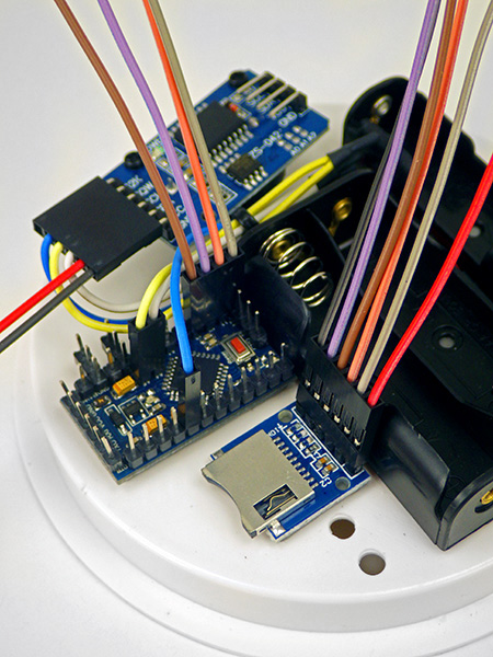
 This build uses a different SD card adapter than previous builds and I’ve changed the resistor location to make the overall assembly easier for beginners.This comes at the expense of having more wires to deal with on the limited real-estate of the knock-out cap platform, and re-positioning the modules to make room for the overhang of the DuPont connector housings. The overall result is a little uglier, and not as robust to knocking about as a unit where every connection is soldered in place, but the platform takes about a third less time to build (~2.5h) with a part cost under ten bucks before you add sensors.
PARTS & MATERIALS

 |
|||||
|---|---|---|---|---|---|
| Parts Total | $8.25 | ||||
| Pro Mini Style clone 3.3v 8mHz | $1.80 | ||||
| DS3231 IIC RTC with 4K AT24C32 EEprom (zs-042) Some ship with CR2032 batteries which will pop if you don’t disable the charging circuit! |
$1.25 | ||||
| SPI Mini SD card Module for Arduino AVR Be sure to buy the ones with four ‘separate’ pull-up resistors. |
$0.50 | ||||
| 20cm Dupont Ribbon Cable 40pin F-F 2.54mm You use ~1/2 of a 20cm cable per logger. Get the ones without the shrouds to save time. |
$0.70 | ||||
| 2xAA Battery Holder & 1xAA Battery holder | $0.60/both | ||||
| CR2032 lithium battery | $0.40 | ||||
| 4″ Knock-Out Test Cap | $0.40 | ||||
| Deans Ultra-T Style Battery Connector Plug | $0.30 | ||||
| 2x Nylon M2 12mm standoff, Nut & Screw M2 5mm | $0.40 | ||||
| Micro SD card 64mb-1gb Older Sandisk cards have lower sleep currents. Test used cards well before putting them in service. |
$1.00 | ||||
| Dupont Crimp Pins & Housings Most parts cost about a 1-2 cents each, after you buy the crimping tool. |
$0.30 | ||||
| Common Cathode Bright RGB LED 5mm A brighter bulb lets you use a larger limit resistor for the same light output. |
$0.10 | ||||
| Double Sided Tape, 2x 4.7MΩ resistors, 26awg silicone wire, (104) 0.1uF caps, 4″ cable ties, heat shrink tubing, header pins, etc…etc… | $0.50 | ||||
| Donation to Arduino.cc It is now possible to build a decent data logger for less than $9 because of the hard work of many people around the world. If you don’t use a ‘real’ Promini from Sparkfun to build your logger, you should at least consider sending a buck or two back to the mothership to keep the open source hardware movement going…so more cool stuff like this can happen! |
$1.00 | ||||
| Comment: And a few tools you might need to get started: (not included in the total above) | |||||
| CP2102 USB-UART Bridge module This 6-pin connector module was specifically designed for compatibility with the Pro Mini. (note that most 2102 boards are not because they only have 5 pins) and these boards work with Mac & Windows after you install the drivers Or for a safer option you could use the FTDI chip version. ***Be sure to confirm any UART board is set to 3.3v before using it!*** |
$2.20 | ||||
| Yihua 936b soldering station 110v These have enough power to solder the large battery connectors. Get extra handles & tips. |
$23.00 | ||||
| DT-830D Digital Multimeter | $3.00 | ||||
| Heaterizer XL-3000 Heat Gun | $14.00 | ||||
| SN-01BM Crimping tool | $22.00 | ||||
COMPONENT PREPARATION
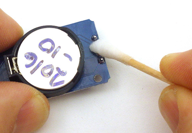
CLEANING: Boards from reputable vendors like Adafruit / Sparkfun are usually clean, but cheap eBay modules are often covered with leftover flux from the manufacturing process and dirty contacts are guaranteed to corrode. Most of us use 90% isopropyl alcohol to clean this residue, but some prefer Polyclens brush cleaner. A couple of five minute sessions in an ultrasonic bath with Iso90 usually works great, but you can also do it by hand with a cotton swab, etc. (Never put vibration sensitive components like accelerometers into an ultrasonic bath)
Preparing the Main Board:
Begin by soldering header pins into place on the 3.3v Pro Mini style board. This is much easier to do if you use a small breadboard to hold the pins in place, however you should not use that breadboard for anything else afterward because the transferred heat will ruin the contacts. I have a few of these old “for soldering only” breadboards lying around. I prefer to use clone boards with A4-A7 broken out to the edges of the board to make the soldering the pin headers a bit easier, but those are not always available. {Click on any images to see larger versions.}
Lay out the required header pins as in the images below. Arrange the pins for the sides of the Pro Mini board on a breadboard so that the two 3x rows extend sideways from the main board at the VCC line and the GND line on the analog side of the Arduino. This is a little tricky because you are working from the bottom of the board, not the top, so there is a left right side transformation. Also note that you can add more sidecar headers than I’ve shown here if your logger will need more connections to the power rails to supply sensors.
{Click on any of the images below to see larger versions.}
 |
 |
 |
Solder the straight riser pins into place along each edge. Then add a tiny amount of flux to the extra header pins and coat the ends of the pins with solder. Tin the wire on one end of a resistor and solder it to the GND header pin on the Pro Mini.
 |
 |
 |
Then weave the resistor leg through the sidecar pins and use that wire to bridge the solder connection to all of the sidecar pins beside the ground pin on the Pro Mini. Repeat the procedure again for the VCC sidecar headers. Use a good amount of solder here to bridge the pins. The sidecar pins are a bit fragile since they are not attached to the module, and could be accidentally broken when attaching Dupont connectors later on unless you provide some extra mechanical support with solder.
 |
 |
 |
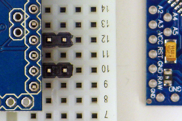
Now that the risers along the sides of the Pro Mini board are in place, we tackle the other riser pins on the board. These are a bit trickier because the A4 & A5 riser pins (needed for the I2C interface) are not aligned with standard breadboard pin spacing. Place the remaining pins into the board face up, then carefully turn the board over onto a flat surface making sure the loose pins stay in place.
 |
 |
 |
It is good to have the six serial UART I/O pins bent slightly away from the other risers to make more room for connecting the UART board. Once the pins are in place clean the flux residue on the bottom of the board with some 90% isopropyl alcohol and a cotton swab.

On the adapter in this picture, the USB to TTL adapter pins are in the reverse order of the Pro Mini style board. This is a fairly common issue with clone boards and simply requires that you flip the adapter. I have connected 3.3v boards the wrong way round many, many times, and not one of them has been harmed by the temporary polarity reversal.
Before proceeding further with your logger build, take a few moments and connect the board to your computer via the UART adapter to test it out by uploading the Blink sketch. You need to install drivers to get the serial communications adapter working with your operating system, and this part of the process can be challenging for people who have never done that before. There are well written guides at Sparkfun & Adafruit if you are using boards with the FT232RL chip from FTDI. If you are using this CP2102 from Silicon Labs then you need to sort out driver installation on your own, but a quick google search should bring up lots of guides posted around the web. Once you have the drivers installed, the Arduino IDE should display a new com port when the adapter is plugged in to the usb port of your computer. At that point you can upload sketches to your Arduino through the serial adapter after selecting Board: Arduino Pro or Pro Mini and ATmega328(3.3v, 8mhz) in addition to the new com port provided by the drivers. If you are ordering parts from eBay, then buy at least three of everything – it’s not uncommon to see a 10-15% failure rate on these budget parts…that’s why they are so cheap. I also order those backup parts from different vendors, since some will take months to ship, while others get the modules to you in a week.
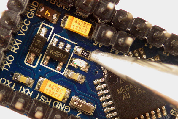
Once you have confirmed that the board is working, remove the power LED limit resistor and the resistor for the LED on pin 13. Simply hold the tip of the iron on one side of the small resistor and apply a gentle sideways pressure. When enough heat has conducted through the resistor, the solder will melt and you should be able to simply ‘flick’ the resistor off the board. Disabling these LEDs conserves battery power. (Note: these limit resistors are in different locations from one Arduino compatible board to the next, so you might have to hunt around to find them.)
 Power LED limit Resistor |
 Pin 13 limit resistor |
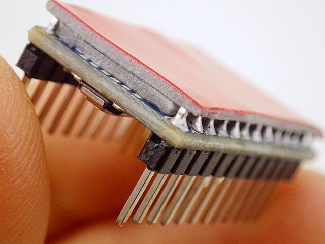
Trim the A4 & A5 pins flush to the board with a pair of side snips. Add two layers of double sided tape to the underside of the Arduino board so that it can be affixed to the platform. Due to the riser pins extending along the side of the pro-mini, two layers are needed: The first layer should fit “between the pins” and the second layer should extend past the pins to the outer edges of the board.
 |
 |
 |
The RTC Module:
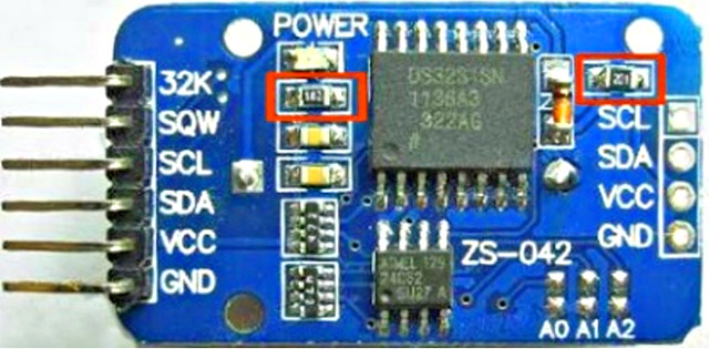
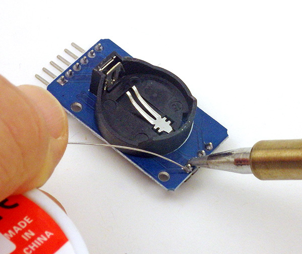
I don’t recommend using LIR2032 rechargeable batteries with this module as the charging circuit wastes a great deal of power, and a CR2032 will backup the RTC for many years. Remove the charging circuit resistor and power LED limit resistor from the circuit board indicated with the red squares in the first picture below. Next add four 90-degree header pins to the I2C cascade port on the RTC board. These four pins will become the connection point for any I2C sensors you add to the data logger:
 |
 |
 |
 |
 |
 |
Since the RTC board already has 4.7k pullups on the SDA (data) and SCL (clock) lines, you will not need to add them to your I2C sensors. This board also has a 4.7k pullup on the SQW alarm line. The GND and VCC pins (3.3v) on that cascade port can also be tapped to power other sensors you connect to the data logger.
The SD Card Adapter:
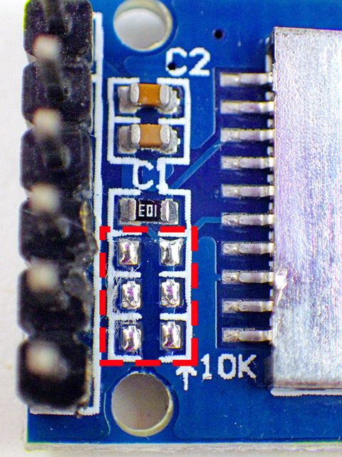
This SD card module comes with small surface mount pullup resistors on the MOSI, MISO & SCK (clock) lines (which have already been removed from the dashed red line area in the diagram). The Arduino SDfat library uses SPI mode 0 communication, which sets the SCK line low when the logger is sleeping. This would cause a constant drain (~0.33mA) through the 10K SCK pullup on the module (second smd from the bottom) if we did not remove it. I prefer to pull MOSI & MISO high using the internal pullups on the ProMini’s 328P processor, so those physical resistors on the breakout board can also be removed. But be careful to leave the top-most resistor of the four in place to pull up the DAT1 & DAT2 lines. This keeps those unused pins on the μSD card from floating when the cards are accessed in SPI mode.
 |
 |
 |
Then add a layer of double sided tape to the bottom of the SD card module and trim it to size.
Dupont Connectors:
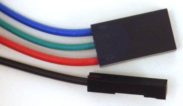
 The RTC & SD card modules will be connected to the Arduino by custom jumpers that you assemble from a 20cm, 40pin F-F Dupont style ribbon cable and 0.1″ (2.54mm) crimp connector housings. Test your cable for end-to-end continuity, then cut the cable into three sections. Then peel off individual 10cm wires and insert them into the black crimp connector ends to create the cables shown. The longer 20cm wires can be used later when we assemble the LED indicator cable, and for other sensor attachments.

| For the I2C connections: Blue: SQW alarm signal. Yellow: SCL (clock) (to A4) White: SDA (data) (to A5) RED: 3.3v regulated BLACK: Ground |
For the SPI cables: RED: 3.3v regulated Grey: Cable select (to D10) Orange: MOSI (to D11) Brown: SClocK (to D13) Purple: MISO (to D12) BLACK: Ground |
I’ve left one of the six RTC connector shroud slots empty for future use with the 32K clock signal but you can change that to a 5-pin housing if you wish. Single 0.1″ (2.54mm) crimp connector housings are shown on the ends of the red, black and blue wires ,but I find that putting heat shrink over single-wire DuPonts help them hold onto the pins better.
ASSEMBLING THE LOGGER PLATFORM
Attach Battery Holders & solder in series
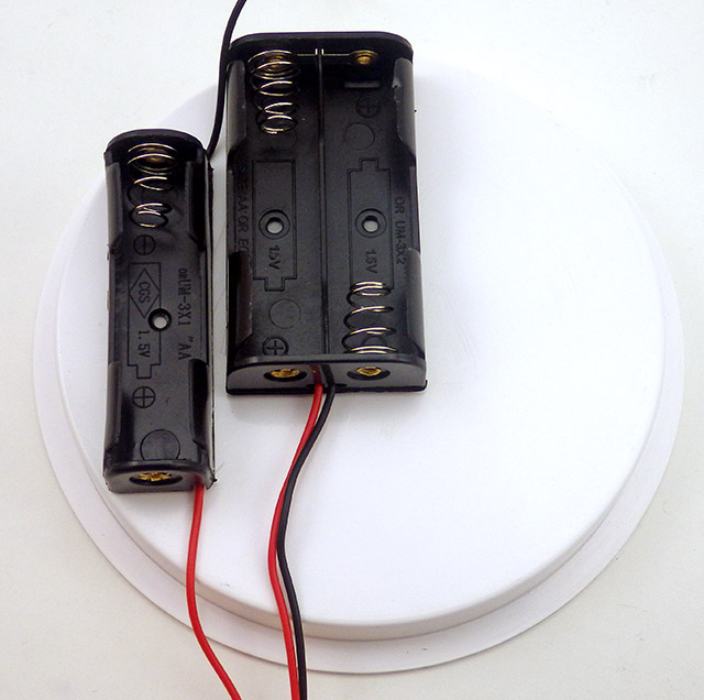
On a 4” PVC knockout cap, arrange your battery holders as close to the edge as possible to maximize room for other parts on the platform, without letting the holders hang off the edge. Mount the battery holders in place with double sided tape.
Join the red wire from the bottom of the single battery holder to the black wire from the double battery holder, so that the three AA batteries are connected in series. Fold the soldered joint and the long RED wire into the gap between the battery holders. Use some heat-shrink to bind them so they stay together inside the gap. Mark and drill 1/8” pair of holes so that you can tie down the wires from the battery pack neatly. Secure the wires to the cap with a zip tie through the holes.
 |
 |
 |
Risers & Tie Downs
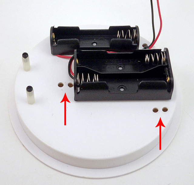
Place the RTC board alongside the batteries with one corner near, but not extending over, the edge of the cap. You want the back edge (with the four-wire cascade port) as close as possible to the single battery holder and the outer edge of the platform. The larger 6-pin connector side of the RTC module will be at a slight angle to make room for the long connector housing that will be placed over those pins. Mark two places for the nylon standoffs and drill 2mm holes through the knockout cap. Thread the nylon standoffs through the holes and attach them to the platform with the plastic nut on the underside of the cap.
Then add two pairs of ¼ inch holes in the platform to be used later to tie-down the connector cables:
 |
 |
 |
Battery Pack Connector
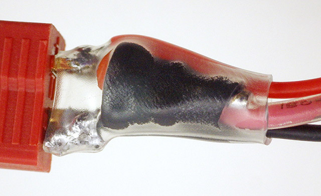
Join the two pieces of the Deans battery connector, and add solder to the end tabs of the female side of the square battery connector. For big connectors like this I turn the iron up to ~700°F (370°C). Be sure to heat the part long enough for the solder to “flow” like a liquid, and for the flux to burn off, but not so long that the nylon starts melting. Then trim the battery wires so that they extend to a mid-point over the battery holders on the platform. Strip about 5mm of insulation from the wires and tin the ends. Build up some extra insulation thickness to protect the wires from bending stress by adding two or more layers of heat shrink to the wires just before the tinned ends. Thread two larger pieces of heat shrink over the wires and then solder the wires to the connector and seal the heat shrink over the exposed metal:
 |
 |
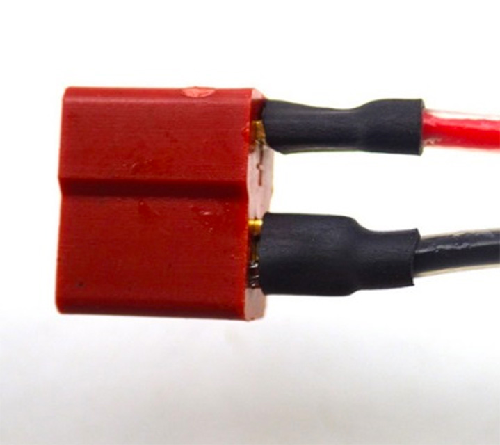 |
Note: the top of the ‘T’ shape on this connector is the positive (red wire) side. Set your iron back down to ~600°F(315°C) after you get the solder on the big connector tabs. As a general rule: the smaller the component – the less time it can withstand heat. It’s not unusual to see maximum tolerances of 5 sec @ 288C for tiny SMD’s.
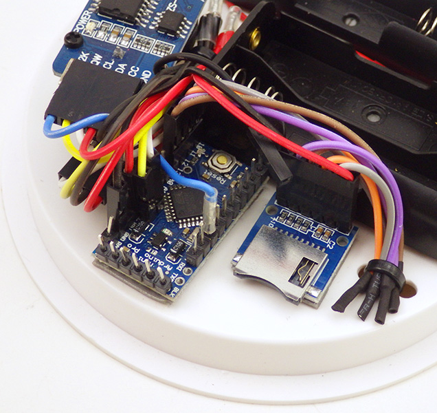
Attach modules to the platform
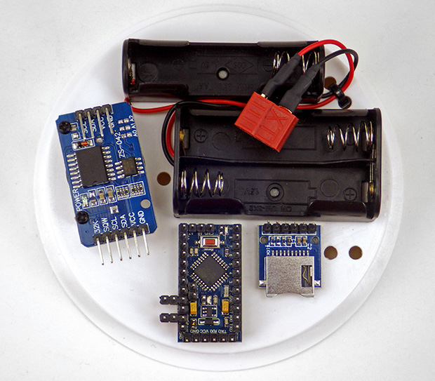
Layout of main components on the 4 inch knock-out cap.
Remove the tape backing from the pro-mini and the SD card adapter and affix them to the platform. As you can see the space is pretty tight. The SD card adapter needs to be close to the battery holder, because the SDcard will extend another 5mm from the holder itself, and this must not extend past the edge of the disk.
Then attach the RTC board to the nylon risers. Check to make sure there is good clearance between the RTC pins and the Arduino pins.
Connect the RTC
After the modules are placed on the board begin the interconnections by affixing the I2C cables to the RTC. Then add the white & yellow two wire connector to risers on A4 (white) and A5 (yellow) of the promini board. Gather the white wires and pull them into the gap between the RTC module and the battery holders. Trim the wires as a group, so that their length just reaches the single battery holder. Then strip, twist & solder the ends of the wires together, and cover the join with heat-shrink.
 |
 |
 |
Repeat the process with the yellow wires, and thread the joined wire sets through a cable tie that is routed from the bottom of the platform. Do not tighten the cable tie loop too much, as the black and red power lines will go through that later. To finish the RTC connection, plug a single blue wire to pin D2 on the Arduino [int(0)], and connect it to the blue RTC alarm line as you did for the other lines. Wrap the soldered join with heat shrink and thread it under the cable tie with the I2C bus wires.
Connect the SD card
Now we will join the SPI lines which connect the SD card adapter to four pins on the Arduino. Connect the 4-wire SPI cable to pins D10-D13 of the Arduino so that the grey wire is connected to D10 and the brown wire is on pin D13. Attach the 6-wire SPI cable to the SD card adapter so that the black ground wire is closest to the pro-mini board.
 |
 |
 |
Take each matching color pair of wires and fold them over beside the SD adapter board. Strip, twist & solder the ends together and add heat shrink to the join. Then bind them to the platform with a cable tie.
Join the Power Rails
The final step for the platform interconnecting cable is to join the “power rails”. Connect a single red jumper to the VCC pin on the Arduino compatible board, and add a single black jumper wire to the GND pin (behind the yellow wire on A5). Then gather ALL the black wires together and trim them to length along the same channel used for the three RTC wires. Strip, twist & solder the black wires together.
Repeat the procedure for the red (+3.3v) Vcc lines. After soldering the ends of these bundles together, cinch them out of the way with the same cable tie that you left loosely holding the RTC connection wires earlier:
 |
 |
 |
Battery Connection with Voltage Divider
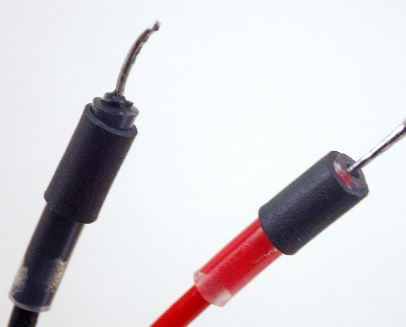
Note: The battery connection wires see a lot of handling compared to the other connections on the logger platform. Since I have crimping pliers to add my own DuPont ends, this is one place on the build where I prefer to use silicone wire that is more flexible than the PVC insulated wire.
With the main interconnect wires completed the last part of the logger platform build is the Arduino side power connector. Put the male battery connector in a vise with a spare female side connected to prevent the nylon from sagging due to heat, then add solder to the terminal flaps of the male battery connector. You might need to turn your iron up to 700°F to tin the connections the large connector, but turn it back down to 600°F (315°C) before attaching the voltage divider resistors, or you will cook those smaller components.
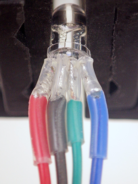
Build a voltage divider from two 4.7MΩ resistors, bridging across the low side resistor with a 0.1µF (104) ceramic capacitor. Add a black wire to the capacitor side of the divider, a pink wire to the center, and a red wire to the opposite side. Then solder this divider across the pins on the male battery connector, being sure to connect the black wire side to the ground pin, and the red wire side to the (+) pin. Blow on the solder to cool it down as soon as the join to the connector pins is complete: there is more than enough residual heat stored in the battery connector plates to cook the little capacitor, which then usually becomes a short.
 |
 |
 |
This voltage divider will cut the battery voltage in half, allowing us to read the status of the 3xAA battery pack on any analog input pin (via the pink wire in the photos above) even though the main battery voltage is above the Arduino’s 3.3v Aref. The 4.7Meg resistors are large enough to limit losses on the bridge (to about 0.6uA), and because they exceed the input impedance limit of the ADC, the capacitor is needed to provide electrons to fill the ADC’s sample and hold capacitor when a reading is needed. The battery voltage calculation for this combination is: float batteryVoltage = float((analogRead(A0)/ 511.5)*3.3); The default MIC5205 regulator found on most promini style boards has ~200-300 mv dropout during SD card writes, so when your AA battery pack gets down 3.65 volts, it’s time to shut down the logger.
Add heat shrink to protect the connections, and then plug the connector into it’s mate on the logger platform. Trim the black wire to length for the ground pin beside D2 (with the blue RTC alarm wire) , and then add a female crimp connector to that wire. Do the same for the pink voltage divider wire which gets attached to your choice of analog inputs from A0-A3, and the red battery wire which gets attached to the RAW input pin near the serial/UART terminal.
 |
 |
 |
Indicator LED
Since we removed the pin 13 LED from the pro-mini, we will now construct an external indicator. This is another place where soft silicone wires are preferred, but if you do not have them, peel away 20cm Red, Green, Blue and Black ribbon cable wires and solder them into place on a common cathode RGB LED, matching the wire colors to the correct pin. Then add stiff heat shrink around the connection points to protect the wire from flexing. Place the ends of the Red, Green and Blue wires into a 3-connector housing. The R-G-B connector attaches to digital pins 4-5-6 on the Arduino.
Cut the black wire near its mid-point, and insert a 20K resistor to limit the current through the LED. I often replace the bottom half of the wire with a softer flexible length of wire with a MALE crimp connector at its end. The male ground pin connects to the ground pin beside the D2 connector.
 |
 |
 |
The MAIN LOGGER PLATFORM is complete
Typical pro-mini loggers built with this design sleep at 0.25mA, before extra sensors are added. At that current draw, the logger should deliver at least eight months of operation on three brand new AA batteries with a 15min duty cycle; depending on sensor load.
Now you can run testing utilities to verify that everything is working. But before you jump into that it’s worth keeping in mind that the entire construction can easily be disassembled for debugging if you suspect a bad connection somewhere, and it is even possible to pop the modules off with a small screwdriver and replace them:

Test continuity on suspect wires with a DVM. If you carefully lift the little tabs holding the crimps inside the black housings, individual wires can be extracted from the connectors and replaced. If your crimps don’t feel like they are securely in place when they slide over the riser pins – then you should replace that connector.
SENSORS & HOUSING
 You can build a robust, inexpensive waterproof housing for your logger from a couple of 4″ plumbing end-caps. I use Loctite E30-CL to pot sensors on the exterior of the housing and you can see a complete walk through of the process in the Sensors & Housing post from last year. Note that I did not use the 4-pin Deans connectors you see there on this newer build because they are fairly expensive, and a few people have been having a hard time getting their hands on them. If you shell out for crimping pliers, you can make as many custom connectors as you need for pennies each. Dupont’s are not as robust, but I’ve had loggers running for years with them, so they are not a bad place to start. If the male pins don’t mate tightly, put a thin layer of solder on them to make them a bit thicker. Quality varies quite a bit, and Pololu sells good crimp pins.
TESTING THE LOGGER
1. Test the LED
Connect your indicator LED, to pins 4(R) – 5(B) – 6(G), and the ground line to one of your spare GND connections. Open Blink with the LED connected to the Arduino. Change the LED to Pin 4. Verify and upload. The red LED should start flashing. Repeat with pins 5 and 6 to test green & blue respectively. Note that with the common ground connection, you can not light up two colors of the LED at the same time.

You can make non reversible sensor connectors by mixing male & female pins in the same housing. But never use male pins on wires that supply power to a sensor circuit, or the connector could short out if those pins come into contact with a conductive surface.
2. Test the I2C bus
Use an I2C scanner to determine if your devices are responding on the I2C bus. With the scanner running, specify P to return to output only the addresses that have devices, and specify S to run a Single Scan. The 4k AT24C32 eeprom on the RTC board is at address 0x57 and the DS3231 will show up at address 0x68. The 32K eeprom should show up at 0x50 and other sensors will show up at different addresses. Note that the 4K AT24C32 is only rated for 100khz operation, but the DS3231 is rated for 400khz bus speeds.
3. Test the RTC
Use the settime & gettime scripts to set and check the time on the RTC. Generally, I set my windows computer to UTC before uploading setTime so that the logger is operating on UTC. This is not possible on a Macintosh, so you will have to check if London time is currently in sync with GMT/UTC, or find some other city that is. Alternatively you could avoid the problem by using the new serial setting script from Mr Alvin’s gitHub.
4. Test μSD Card communication
Insert the microSD in the adapter and test it with the CARDinfo utility at the Arduino playground. Remember to change the CSelect variable to 10 to get the CARDino to operate properly, as that is the pin we connected to the μSD card Cable Select line.

Loggers with the default pro-mini’s MIC5205 regulator usually delivers sleep current in the 0.21-0.26mA range depending on the SD card (Promini~0.07mA, SDcard: ~0.05-0.1mA, RTC~0.09mA) That should give you at least eight months of operation on 3xAA’s, and with minor modifications you can pull that down into the 0.15mA range to run almost two years. (Or you could pass the one year mark by powering the logger with 4xAA cells in series. If you do this you will have to change the resistor ratio on the main battery voltage divider to keep it’s output below the 3.3v aref voltage on the analog input pins. For higher input voltages I use a 3.3/10 Meg Ohm combination) Write the build date & your initial sleep current on the bottom of the logger platform – it’s a handy piece of diagnostic information to have later.
5. Test the EEprom(s)
A utility to test I2C eeproms was posted by bHogan at the Arduino playground forum, but that version is now quite old and does not compile in the current IDE without editing. I’ve posted an updated version on gitHub. Setting #define EEPROM_ADDR 0x57 will test the 4k eeprom on the RTC board, and if you install the extra 32k eeprom that shows up on the bus at 0x50. The serial window will return A through T & 33 through 48 if the eeprom being tested is working OK.
6. Check Sleep Current
#include the LowPower.h library from RocketScream at the beginning of a blank sketch and the put the following line at the beginning of the main loop:
LowPower.powerDown(SLEEP_FOREVER, ADC_OFF, BOD_ON);
Then enable some internal pull-up resistors in to the setup section of your code:
(be sure to do this before you call sd.begin)
// Always pullup CS:
pinMode(chipSelect, OUTPUT); digitalWrite(chipSelect, HIGH); //pullup the CS pin to tell the SD card go to sleep
//and you may need to pullup MOSI/MISO lines:
//pinMode(MOSIpin, OUTPUT); digitalWrite(MOSIpin, HIGH);
//pinMode(MISOpin, INPUT); digitalWrite(MISOpin, HIGH);
Upload that sketch and your logger will be put to sleep as soon as the program runs. Note: the CS line should have a pullup when using the standard SD libraries, and the MOSI/MISO lines may also need to be enabled to lower the sleep current with some SD cards. But SPI is a complex protocol, and you might have to turn off these pull-ups if you have other SPI sensors attached.
7. Build your datalogger code
A good place to start would be Tom Igoe’s analog pin reading example at Arduino.cc ( be sure const int chipSelect = 10; for the build described in this tutorial) and there is a nifty little function for automatically creating log file names over on Adafruit’s site. For something a little more advanced, I have prepared a basic data logger script that puts the data logger to sleep and wakes it up again based on timed alarms from the real time clock. These are all just starting points for you to add to as you learn more about programming an Arduino.
The first major thing to tackle to achieve a decent operating lifespan is buffering your sensor data to the 100 kHz 4k EEprom on the RTC board. Examples of the code I use for this eeprom buffering is embedded the I2C eeprom tester example I’ve placed on gitHub. You don’t want to wake up the card more than once per day, since that operation draws up to 100mA, for 200-400ms, which is more than any other run-time power use on the logger. Older Sandisk cards (<1Gb) tend to have lower sleep currents around 70µA, but it’s not unusual to see newer large capacity cards drawing ~200µA or more during sleep.
You can extend that power saving strategy by adding a larger 32K AT24C256 EEprom to the logger platform. Because all I2C devices use the same bus wires, simply add the four EEprom connections to the bundles as you make them:
 |
 |
 |
In addition to saving power by reducing the number of SD write events, the larger EEprom also extends the operating lifespan by allowing you to safely accelerate the I2C bus to 400khz, and this can reduce run-time duty cycle length significantly. Because all I2C bus devices are connected in parallel, simply add the four EEprom jumpers to the appropriate wire bundles as you make them. Alternatively, you could add a high resolution temperature sensor like the TMP102, or the MCP9808 to the logger in exactly the same way.
To fully optimize your code it is helpful monitor current during “logging events”, but this usually requires an oscilloscope. In this post, I have outlined a method to use an UNO with the serial monitor built into the IDE to capture and display these brief events.
Addendum 2017-06-22
I wouldn’t bother for just one or two builds, but Dangerous prototypes just introduced a Dirty Cables service to order custom cables. Be interesting if I could build something like this logger interconnect wire with their tool. Might be a good way to throw a few kits up on Tindie…

Unless I am missing something, it seems that you could make a PCB for this. I use OshPark, where I get three copies of a design for $5 sq in. This would be an irregular shape, so the price would be based on the smallest rectangle that the PCB would fit inside. You could minimize the PCB size (maybe 2 x 1.8″, or $18 for 3) if you mounted the battery holders above the completed PCB, maybe with standoffs or with a 3D printed fixture.
Yes, that would be a good approach if time&efficiency was what I was after. But this “jumpers & modules” approach is aimed at classroom settings where the experience of building the thing is as important as the end product. Keep in mind that most of our students have never even held a soldering iron before. Also the jumpers approach gives you flexibility to integrate other components like I2C sensors into the build with little effort (see the photo with the added EEprom further down the page – that could just as easily be a temp or humidity sensor). I wanted a plan that you could make with any 3.3v “mini-style” board, since part availability changes over time and pin arrangements vary considerably. And finally there are other modifications to integrate to this build, which I will post here if I get the time. Basically, the goal was to create something cheap & flexible, rather than completely optimized.
Excellent approach for the classroom. I was under the impression that you spent most of your time slogging through the jungles of Belize or Guatemala tossing data loggers into tide pools! I follow you because I do a lot of domestic data logging, for green building efficiency, etc.
Pingback: DIY Arduino ProMini Data Logger - Electronics-Lab
I think there is room for both approaches in the user community. The breadboard version is more flexible and provides education opportunities, but some of us are more interested in having reliable and compact designs so we can move ahead and collect our data. I’m not sure there’s enough of a market to make it worth Ed’s time to do the PCBs, but I’d buy them from him in a heartbeat.
Given the number of “promini” shield projects already out there (eg: Pawelsky@OSHpark) I’m surprised someone hasn’t already done it, or taken the stuff I’ve released and produced logger kits with the screw headers idea. And it continues to be a mystery why the folks at Adafruit & Sparkfun are not putting better power optimisation into the design of their off the shelf loggers like the Feather 32u4 Adalogger or in ‘snap-together’ solutions Tinyduino & MicroDuino. If I could get those down below 0.15mA sleep currents (w sensors, sd, etc. attached) and provide the voltage regulation that my sensors require, then I’d be buying them instead of building.
But the other issue is that I’m not through the dev stage yet and there are several major features I want to add to every data logger I build. So I’m not going to do a big run of boards at the half way point. When you see my next post, you will see what I mean.
That was my guess. You keep doing the R&D, and maybe an engineer will come along to commoditize what you’ve learned.
That does seem to be the emerging pattern as the open source hardware movement matures. Which kind of says something about what’s happened to corporate R&D since the glory days of Bell labs & Xerox Parc. But I’m sure the stuff I’ve cobbled together would be a trivial exercise for anyone with an engineering background, so I’m not too worried about it. And one of my goals is to get loggers into the hands of people who probably wouldn’t qualify as “profitable” markets anyway. I’ve been to many places where folks have no decent research kit, and they are not likely to get it any time soon unless they make it themselves. But their need for data about their environment is, if anything, even more pressing. Groups like PublicLab & Hackteria keep me optimistic that the makers movement will help address the situation.
If you take hourly measurements for temperatures, humidity and pressure there is enough energy? Whats the lifetime for battery?
Datalogger lifespan depends on sleep current more than any other factor, by a very large margin. A typical pro mini build, without eeprom buffering, or pin-powering the RTC, usually comes in around 0.25mA sleep current. That gets you out to between 6-8 months on 3xAA’s, and a bit longer with Lithium AA’s. This can be affected quite a bit by using older low current SD cards, but I find that the number of readings per hour is less of a factor than you would think; especially if you have good sensors that automatically go to sleep between readings. I outline power optimization strategies in Part 4 of the build series, but if you are just starting out you can simply add another bank of 3xAA batteries in parallel with the first bank, and that should get you out to 1 year of operation. The extra bank can be put on the underside of the platform. Be sure to isolate the two banks from each other with a couple of 1N5817 Shottky diodes.
Another option with Prominis is to use more than 3XAA batteries, since their regulator can take up to a maximum of 12v input. I did not go that route simply because I ran out of space on the platform surface 🙂 6xAA in series you would make it up to about 10.8v (with typical over-voltage of 1.8v per cell at the start). But you need to be careful to check the regulator specifications on the specific Arduino board you are using. Many Arduino clone regulators can not take more than 6-7 volts input, which is why I usually add parallel banks, rather than more batteries in series.
Hi Edward, nice idea for the nano-datalogger shield.
I’m actually trying out Feather adalogger boards by Adafruit, who also created a DS3231 shield in breakout form and in Featherwing version ( https://blog.adafruit.com/2016/02/17/new-products-ds3231-precision-rtc-featherwing-adalogger-featherwing/ ).
Switching from the 32u4 based Feather to the Feather M0 variant seems even more interesting, because the M0 version is based on ATSAMD21, which has its own 32kHz RTC (and not announced on Adafruit’s own product page, though!).
Another M0 advantage is that you can mux-up the pins to get 6 SerCom ports because, I’m condamned to using multiple SPI for my gas sensors ( https://learn.adafruit.com/using-atsamd21-sercom-to-add-more-spi-i2c-serial-ports/muxing-it-up ).
Finally, I guess it could be interesting to stick with the Feather M0 adalogger, which seems to be the ultimate all-on-board logger since it’s got RTC, 6 SerComs, plenty of storage, and it’s also integrating the uSD card module ( https://learn.adafruit.com/adafruit-feather-m0-adalogger ).
Just need to add 32k I2C FRAM and scrape off all LED’s…
The Feathers can be powered from the built-in LiPo/usb charging switch, and in this case, the ATSAMD21’s internal RTC keeps being powered when the chip is asleep.
But if you pull down the enable-input of the 3V3 power supply to disable the chip ànd the sensors, you might need to solder on a coincell and diode.
I quite agree that the combination of the the power management & form factor make the Feather a compelling package for $22 if you are doing multiple builds. But from the perspective of time vs productivity, that was already true for the Sparkfun Openlog, TinyDuino’s & Microduinos, though I think the feather makes a nicer overall design. The Cave Pearl builds that we are releasing are also aimed at teaching environments where having students go through the steps to make something with their own hands, is a part of the learning process. For my high-school teaching friends, the difference between $10 & $36 per logger also matters, as they are funding everything out of their own pockets.
On a different level, I only spend about 2 hours per unit assembling the logger platforms, so the real time investment is mostly on housings, coding, and increasingly: sensor calibration. When we started the project, every new logger was a significant advance in the amount of data we could gather, but now that we are maxing out the number of units we can service on field visits, it’s about modifying the builds for different applications. In that regard, I’m still happy with the flexibility jumpers & wires approach, even if it’s not the most time efficient. When I finish my power tweaking with the 328P based boards (more on that later…), I’m guessing that sleep current will be pretty similar no matter which microcontroller we go with. I’ll still be very interested to hear what kind of operating life you get with the feather based loggers, and if you run into challenges flying with lipo batteries. Over here, AA alkaline cells are the only batteries that don’t give us grief at the airport.
I need some advice. I have built the logger as the schematics above show and am using your basic datalogger script(Uno breadboard datalogger) in the link above.
Everything works really well, just as I want.
But I am think I am missing something, the arduino is put to sleep but the DS3231 using the same current anyway 0.6 mA, way higher than you mentioned above( RTC~0.09mA).
I have removed the two resistors on the RTC board as you described.
What am I missing or do you think I have a faulty RTC?
Swapping hardware should always be your first debugging step when you are using dodgy 99¢ parts from eBay. I never order less than three of anything just so I can do this. 0.6mA is very large for an RTC that normally draws about 0.1mA. It’s possible the chip is bad, but also that there is a solder bridge somewhere leaking power. I’ve see lots of re-flow errors on those boards at the legs of the 3231, and also at the two little banks of pullup resistors. Sometimes you can fix those by working your way along the contact points with the tip of an iron & remelting the solder at each point.
hmmm, I first tried to resolder the contact points while waiting for new ones to arrive with no luck. I now have tried 3 different DS3231, and they all use 0.57- 0.6mA. I must be doing something wrong, they should not all be faulty. They do not seem to go to sleep but draw constant high current even when the Arduino is sleeping.
How much power does the rtc board draw when it’s connected to power only, and not connected to the Arduino? Remember that those boards have pullup resistors on SDA, SCL, and SQW – if those lines get pulled low by the Arduino while it’s sleeping , power will constantly flow through those resistors.
If I disconnect all other cables to the rtc and power it directly with 3,3v it still uses 0.55-0.6mA.
I am considering to powering off the rtc during sleep by supplying power through a controlled digital pin. Hopefully it will still send a wake up signal, powered by the on board battery.
Your boards have some kind of defect. I’d order others from a different supplier.
The 3 boards I tested, were from two different suppliers. I have ordered more from different suppliers and I will let you know how that turns out when I get them. Thank you for your help!
I know this is a bit late. But it might help. It is normal for any of those Dallas RTCs to draw the mentioned current when power goes to Vdd. To achieve the standby current of under 1uA the Vdd pin must be powered down and the pullups on the I2C Bus. I would suggest to use one of the uC port lines to power Vdd and bring the I2C Pullup lines low during sleep. This method works very well. I designed a Arduino compatibe 1284P based “bottle logger” with the DS3231 and a SD card interface and it was possible to achieve a sleep current of 15uA at 4.6V supply voltage. The hardware includes a SDI-12 and RS485 interface as well. During sleep The Sd card and RTC are powered down completely. The SD card gets only written to when enough data has been acquired to minimize the SD card power consumption. If you are interested you can find more information on it on the Northen Widget GITHub page. Look for the Bottle Logger Rev2 design pages. I hope the information may be useful to you.
15uA is pretty darned good for an atmel based logger! My best builds (with SD shutdown, and pin powered RTC’s) are usually in the low twenties. But that’s with a sensor or two along for the ride, and God knows what kind of caps on those cheap $2 promini clones I’m using. I also have to swap in an MCP1700 series regulator.
I didn’t cover those mods on the 2016 build, but I review over them in the 2017 screw terminal update for the loggers. Since that was released, I have quit using the pin powering, and I’m now using the charging circuit on the $1 RTC boards to provide power via the Vbat line to force the low sleep currents from of them. You can see that at the end of the RTC module post.
I’m curious about the SDI-12 interface: Are there sensors using that protocol that are not available in I2C or SPI versions?
Great. It looks like all the right things took place. In my case I didn’t have to wrestle with the original board wirings. I connected the Vbat through a Schottky diode OR to both a CR2032 and the logger supply voltage. The Vdd pin gets powered up through an IO pin when the 1284P comes out of sleep. The 32khz SQ triggers a wakupof the logger through a pullup resistor.
BTW. Because most of the 15uA current drain is the result of leakages in the powered up CMOS chips, I tested the logger in a temperature chamber down to -50 Degrees C and observed only 2uA. At +60C it is terrible with over 70uA. THe SD card tested is a industrial 512MB size card from Belkin with a industrial temperature range that I had access to for testing.
The standard conformant SDI-12 interface ties into the 2nd UART of the 1284P and is shared with RS485 and can be used by choice alternatively. I modified the published SDI-12 Arduino library to use hardware serial via the 2nd UART and tested it successfully so far only with a loaned out Decagon soil moisture sensor that I had access to.
The board can be programmed via the integrated FTDI232RL interface and the 1284P bootloader. A interface to a bluetooth radio allows wireless data transfer by bringing a magnet to the side of the bottle, waking up the logger and allowing it connect to a laptop with BT serial setup. This way the logger enclosure does not need to be opened or disturbed. Downside might be, it may take a long time the many MB of data on the SD Card to upload even at higher UART speeds. I haven’t tested this part yet other then the basic functionality.
I have not written any logger aplication code as I was at the time only interested to create a new data logger HW design based on the 1284P to allow larger applications. I had also planned to create a thermocouple expansion scanner board. The bottle logger has a SPI expansion bort to allow extending the hardware capabilities with custom boards such as TCs and perhaps PT100/1000.
Unfortunately, after 2015 I had to look after my ill mother until her death and put on a break in the design. Besides, I intended to leave further SW/HW development work with N.W. as on open source design anybody can take it further.
Anyways, that is basically all that can be said about the project:-)
Correction:
It is the 1PPS output and not the 32kHz RTC pin. Sorry for the typo.
The Arduino IDE can be used to develop the programs. Using the 1284 Arduino extensions, that can be found on the Internet, the 1284 is then supported.
As to Arduino Pro-Mini board selection:
I use them quite a bit for many little projects. When I purchase them on eBay I look for a particular version:
All extra pins (A4,5,6,7) are located between pins D9 and D10 on the bottom narrow side.
It has a replaceable crystal. That is important in two ways: one can choose a particular frequency easily yourself. It has much better frequency stability.
The third reason is, it uses a TQFP package iC instead of QDFN packages, allowing easier access to non bonded pin such as AREF.
I also temove the regulator and remove the LED current limiting resistors to conserve power for battery powered projects. This way the sleep current is below 1uA
One remaining task needs to be done:
All those boards come unfortunately with a watchdog unfriendly bootloader. I recommend to replace the BL with a compatible Optiboot version.
I plan to modify an existing Optiboot BL to operate on frequencies as low as 1Mhz to conserve operating current. I wil report resilts whenever I get to it. Unfortunately it is not easy to use a Windows tool chain and plan to do this under Limux.
Yes I’ve been thinking about those board variants
https://www.ebay.com/itm/1Ps-NEW-Pro-Mini-ATMEGA328P-5V-16M-3-3V-8M-Optional-Arduino-PRO-mini-Compatible/142772185547?hash=item213de2a9cb:g:5MsAAOSwEaNa4bkT
after watching Julian Ilett’s Arduino sandwich build videos:
https://www.youtube.com/watch?v=8ikyp4lu45M&t=194s
but I did not know about the replaceable crystals. I haven’t reached the stage of changing bootloaders / fuses yet, as I’ve not found an application where slow running is better mixing sleeps & normal speed ops.
Hi Ed,
This is the version I had mentioned. I am quite happy with the consistency over 20 boards so far.
https://www.ebay.com/itm/5PCS-Pro-Mini-atmega328-5V-16M-Replace-ATmega128-Arduino-Compatible-with-Nano/311569959184?hash=item488b044910:g:~cYAAOSw42dZNSLD
Watterott in Germany makes a Pro-Mini with a ATMEGA328PB. This uC comes with 2 UARTS, I2C, and SPI peripherals as well as 4 extra IO pins. I bought a few of them and they work great. Here is the link:
https://www.watterott.com/index.php?page=product&info=2424
As to the bootloaders, it is something on my list of todo things. If I am successful, I will share my work of course. I want to expand the watchdog friendly botloaders from 1-4 Mhz. 4Mhz may exist already.
It is my opinion, that the 1294P would be a worthy main stream successor to the 328P due to its greater ressources such as 4 times the flash space and 16k of RAM. With an SDCard fike system ressources get used up rather quickly. With the 1284P more data could be buffered in RAM to minimize SDcard accesses. The Atmel AT45 Series FLASH storage devices might also be useful due to their large sizes. They have only 2uA of sleep current. Here is a link as an example:
Click to access doc2224.pdf
You have a really fascinating project and found many solutions to practical problems and I enjoy finding out what other people are up to. I have no particular science interest, but enjoy developing uC based hardware. I leave the application programmimg to people like you who have a real mission in the field.
Gerhard