
Reading the compass bearing is more important with the open water units, as passage geometry controls flow direction in caves. To see the kind of data we get from these pendulum sensors, see case study #2 in Cave Pearl Data Logger: A Flexible Arduino-Based Logging Platform for Long-Term Monitoring in Harsh Environments In 2020 we released a 3-Part build tutorial based on that paper & in 2023 a 2-Part logger that runs on a coin cell
When I started building a flow sensor based on the drag/tilt principle, I knew that leaving sensors on their default factory calibration settings was not optimal, but I had so many other things to sort out regarding power use, memory handling, etc., that I left calibration to deal with later. Since I could not trust the electronic compass in the units, I simply installed the Pearls with a magnetic compass in my hand, making sure I knew which accelerometer axis was physically aligned North. But once my loggers started consistently reaching a year of operation, that “later” finally arrived. I tackled the topic of calibration with little knowledge beforehand, and there was quite a bit of background material to wade through. Rather than waffle on about it I am simply going to provide links here to some of the better references I came across:
The Sensor Fusion tech talk from InvenSense provides a fairly broad overview
Sensors Online: Compensating for Tilt, Hard-Iron, and Soft-Iron Effects
AN4246: Calibrating an eCompass in the Presence of Hard and Soft-Iron Interference
And if that Freescale paper didn’t leave you in the dust, you could try Alec Myer’s extensive blog entries on magnetometer calibration. But since I haven’t seen a matrix operation since high school, most of that went right over my head. It didn’t help that there are so many different ways of defining a “standard” reference frame, making many code examples hard for a newbie like me to interpret. But even without the math I came away understanding that hard iron shifts the entire sensors output, while soft iron distorts it. So the goal of calibration was to transform displaced eliptical shapes into nice balanced spheres centered on the origin. And I hoped for a way to do this that would work with the many different compasses and accelerometers I had been using since I began development in 2013, because most of those flow sensors are still running.
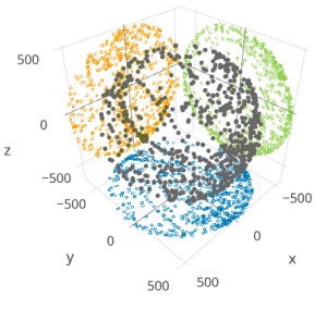
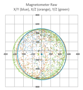
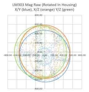
I had a new LM303DLHC breakout from Adafruit that I was considering because it contained both an accelerometer and a compass (having both on the same IC keeps them in alignment), so I used that to generate an initial spread of points by simply ‘waving it around” while it was tethered to one of the loggers. Then I searched for some way to display the points. I found that Plotly makes it easy to upload and visualize data-sets, and it freely rotates the 3D scatter plot via click & drag. This gave me a good overall impression of the “shape” of the data, but I did not see how this would help me quantify a hard-iron offset or spot other subtle distortions. Hidden in the Plotly settings there was a button that projected the data onto the three axis planes. Seeing that sent me back to my spreadsheet, where overlaying these three plots (and adding an circular outline to see the edges better) produced:
Now at least I could see the offsets and the other distortions well enough to compare ‘before & after’. But I still needed to figure out how to actually do a calibration. Google searches turned up plenty of code examples that simply record maximum & minimum values along each axis to determine the hard iron offset. For this “low & high limit” method you rotate the sensor in a circle along each axis a few times, and then find the center point between those two extremes. If the sensor has no offset that center point will be very near zero, but if you find a number different than zero, that number is the hard iron offset. These approaches assume that there is no significant soft iron distortion and judging from the rounded outlines in my graph, that was reasonably true for the naked LM303 board I had been waving around.
But these methods rely on you capturing the extreme values along each axis, and my data was kind of patchy. I needed to work on my Magnetometer Calibration Shuffle if I was going to capture enough points from all possible orientations. Yury Matselenak over at DIY drones offered and an alternative to my hand wavy approach using the sides of a box to calibrate the ubiquitous HMC5883L (you might want to add a leveling table). I thought that looked pretty good until I came across a technical note at the Paperless Cave Surveying site in Switzerland. In A General Calibration Algorithm for 3-Axis Compass/Clinometer Devices it states:
“A cube can be placed with any of the 6 faces up and in each case any of the 4 side faces may be in front, giving a total of 24 orientations. Unfortunately it turns out that 24 measurements are not enough for a good calibration. A perfect set of 60 orientations is contained in the symmetry group of the dodecahedron or icosahedron. However, this set of orientations is not useful in practice because it is too complex to be reproduced in the field.”
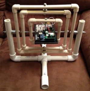
That meant I was going to need a more advanced testing rig. I found plenty of examples on Youtube where people had fashioned fancy calibration rigs out of 3-Axis Camera Gimbals, but they looked expensive, had alot of metal in them, and I was not sure if they were robust enough to transport into the field. Then I found a post by jjspierx over at the Arduino forum, who built a yaw/pitch/roll jig out of PVC for about $20. It’s a really sweet design that could be built to just about any size. I still might make one just for the fun of it, although I think I will use nylon bolts to keep any metal away from the magnetometer.
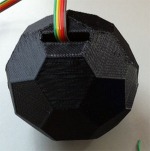
Roger Clark’s approach posted as test_rig.jpg in the thread.
Another elegant solution was posted by Roger Clark over at the Arduino playground. His 3D printed polyhedron allowed him to put an MPU9150 into that ‘perfect set’ of orientations. “Hey” I thought to myself “That’s a Buckyball. I can make that” But as I dug into all the different ways to make a truncated icosohedron I had this niggling idea that somehow I might still be missing something. If this was really all it took, then why did so many people in the quad-copter & robot forums complain that they never got their compasses to work properly? The more of these complaints I found, the more I started to wonder about my sensors being too close to the Arduino, the RTC breakout, and most of all those alkaline batteries.
There was another interesting note about this at the end of that swiss paper:
“Experience shows that calibration must be repeated from time to time to avoid performance degradation due to component drift and aging. In devices using primary batteries, a calibration is needed after each battery change because the battery is unavoidably the main source of magnetic disturbance and new batteries never have exactly the same behavior as the old ones.”
To see exactly how much of a factor this was for my loggers I mounted the LM303 sensor board in one of the underwater housings (which had a 6xAA battery pack about 10 cm from the sensor) and ran another test. The results made it pretty clear that, yes, magnetometers really do need to be calibrated inside their final operating environment. This also showed me that unless I was willing to spring for expensive degaussed batteries, I was going to need software that could provide significant soft iron compensation: the max & min only approaches just weren’t going to cut it. And I need to make sure that the battery & sensor orientations don’t not change during deployment by adding an internal brace to keep things from shifting around. It also occurred to me that there might be some temperature dependencies, but by this point I didn’t want to look under that rock and find there was even more work to do.
After seeing that plot I went back to the idea of building a geodesic frame big enough to contain the whole flow sensor, that could be assembled with zip-ties for transport into the field. And I think I found a way to build one out of tubing, but in the end I simply fashioned a couple of handles that could be connected directly to the threaded ends of my underwater housing. A sliding joint on the top handle allowed me to spin the unit slowly and smoothly as I pivot my body into different positions. The whole process takes about 10 – 15 minutes, using my arms as the calibration jig. This produces a spread of points that look like the blue line plot below:
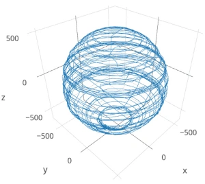
Plotly again, with lines rather than points to show the pattern in the data as I twirled the unit about its long axis. This method only rotates the unit around the Z axis, which shows up quite clearly in the data.
Although this is not the same pattern you get from a 3-axis gimbal rotation, I am reasonably confident that I have captured enough points for a decent calibration. And the handles are easily transported so that I can do some post deployment calibrations in the field on the various different housings.
Although I was still boggled by forum threads discussing the finer points of “Li’s ellipsoid algorithm”, I still had to choose some software to generate the correction factors and I wanted something flexible enough to use with any compass rather than a one-of solution that would leave me tied to a specific sensor.
The best Arduino script example of compass calibration I could find was the Comp6DOF_n0m1 Library by Noah Shibley & Michael Grant (and I will be cribbing heavily from their integer trig functions for roll, pitch & yaw…)
Using the FreeIMU GUI Toolset
A post in Adafruits support forum suggested Varasano’s FreeIMU Calibration Application. The FreeIMU calibration app was written with a GUI, but fortunately Zymotico posted a Youtube video guide that shows how a couple of simple config file edits let you run the FreeIMU GUI Toolset in manual mode:
(These are screen shots from that video)
 These changes allow you to run the application without the GUI, so long as you provide a couple of tab delimited text files of data. The video goes into some detail showing how to use a processing sketch to save serial output from Adafruit 10 DOF IMU as a csv file, but all I did the first few times was copy and paste data directly from the serial window into a spreadsheet, and from there into notepad. (since my units are data loggers, I could use the csv files on the SD cards for the in-housing tests I did afterwards)
 Then you save “acc.txt” and magn.txt” in the FreeIMU GUI folder, right beside the freeimu_manualCal.bat file that you modified earlier. Once you have your data files in place, run “Freeimu_manualCal.bat”. On my machine the GUI still launches – displaying no data, but a command line window also opens:
Note that if you try to run the batch file that you modified with the default data files the program came with you will see NAN (not a number) errors. This is a sign that you did not save your new data files in the right directory, or that your data does not have the correct format. Once you have the FreeIMU Offsets & Scale factors in hand, the calculation is simply:
CalibratedData = ( unCalibratedData – Offset ) / Scaling Factor
When I used this procedure on the battery distorted data from that first housing trial the before and after plots looked like this:
Now that’s what I wanted to see! Even better: FreeIMU generated corrections for both the accelerometer and the magnetometer at the same time. (Units are lost when normalizing the ellipsoid because of the scaling factor. You can get acceleration back by multiplying by 9.80665 m/s*s.)
Unfortunately FreeIMU also comes with a whopping 300MB folder of support files, and with Fabio Varesano’s passing there is a real question about whether his software will continue to be available (or how long it will be updated to prevent some python version dependency problem from cropping up). I have also run across some scary looking hacked pages in the old varesano.net site, so it might be safer to use the wayback machine to search through it.
Using Magneto v1.2
My search for alternatives to FreeIMU lead me to Magneto v1.2 over at the Sailboat Instruments blog That software was recommended by some heavy-hitters at the Sparkfun and the Arduino Playground forums, with one helpful person posting a step by step guide to Calibrating the LM303 with the Magneto software. With my earlier tests, I already had raw magnetometer data in text file, but I did not get good results until I noticed that before Scirus launched Magneto he was preprocessing the raw magnetometer readings with an axes-specific gain correction (See Table 75: Gain Setting on datasheet) to convert the raw output into nano Tesla:
Xm_nanoTesla = rawCompass.m.x*(100000.0/1100.0);
// Gain X [LSB/Gauss] for selected input field range (1.3 in these case)
Ym_nanoTesla = rawCompass.m.y*(100000.0/1100.0);
Zm_nanoTesla = rawCompass.m.z*(100000.0/980.0);
Save this converted data into the Mag_raw.txt file that you open with the Magneto program. Then your numbers match the magnetic field norm (or Total intensity) values that you get from the NOAA or BGS sites:
To use his method with a different magnetometer, you would have to dig into the datasheets, and replace the (100000.0/1100.0) scaling factors with values that convert your specific sensors output into nanoTesla. On the LM303, that factor is different on the Z axis than it is on the X & Y axes. But according to the author on the Sailboat Instruments site you only need to match the total field “norm” values if you want the final output on an absolute scale:
“Magneto expects to receive raw data in +- format (a value of zero indicating a null field in the current axis), but not necessarily normalized to +-1.0.
If your sensors have SPI or I2C outputs, they will usually directly produce the required format. For example, the MicroMag3 magnetometer directly produces counts from -3411 to +3411, and the the SCA3000 accelerometer directly produces counts from -1333 to 1333, and Magneto can process directly these values, without the need to normalize them to +- 1.0. I understand that a normalization may be desirable to avoid machine precision problems, but this has not been the case with these sensors.
If your sensors produce voltage levels that you have to convert to counts with an ADC, you have indeed to subtract a zero field value from the ADC output before using Magneto. You would then normally choose the maximum positive value as input to the ‘Norm of Magnetic or Gravitational field’.
But this norm value is not critical if all you want to calculate later on is a heading (if it is a magnetometer) or a tilt angle (if it is an accelerometer). You can input any reasonable value for the norm, the correction matrix will be different by just a scaling factor, but the calculated heading (or tilt angle) will be the same, as it depends only on the relative value of the field components. The bias values will be unchanged, as they do not depend on the norm.”
Once I had my raw readings at the same scale as the Total Intensity numbers, I could hit the calibrate button, taking care to put the generated correction factors in the right section of the matrix calculation code:
 Rather than simply finding an offset and scale factor for each axis, Magneto creates twelve different calibration values that correct for a whole set of errors: bias, hard iron, scale factor, soft iron and misalignment. As you can see from the example above, this makes calculating the corrected data a bit more involved than with FreeIMU. I am not really sure I want to sandbag my loggers with all that floating point math (mistakes there have given me grief in the past) so I will probably offload these calculations to post processing with Excel. To check that your calculations are working OK, keep in mind that in the absence of any strong local magnetic fields, the maximum readings should reflect the magnetic field of the earth which ranges between 20 and 60 micro-Teslas.
When I ran Magneto on the same data set I tested with FreeIMU, the x/y plots were once again transformed into perfect spheres, centered on the origin. Since I could not determine which software had done a better job by looking at the graphs, I took a hint from the Scirus post and decided to run the post-calibration numbers from each application as input to both programs. Since the FreeIMU “normalized” to unitless +-1 values, I had to multiply it’s output by my local 54,000 nT total field to use it’s post calibration output in Magneto. As you might expect, each program thought it’s own output file was perfect, requiring no further offsets, etc. But Magneto thought there were still “slight” offsets in the corrected data from FreeIMU, while FreeIMU thought the output from Magneto’s corrections were fine. I have slight in quotes there, because Magneto’s suggested bias corrections to the post FreeIMU data amounted to less than 0.1% of the total range. Given all the real world factors that affect compass readings, I’d say the two calibrations are functionally equivalent, although I suspect Magneto can deal with more complicated soft iron distortions.
What about the Accelerometers?
A side benefit of all this is that both programs can be used to calibrate accelerometers as well! FreeIMU does this right from the start, producing unit-less +-1 results. For Magneto you might again need to pre-process your specific raw accelerometer output, taking into account the bit depth and G sensitivity, to convert the data into milliGalileo. Then enter a value of 1000 milliGalileo as the “norm” for the gravitational field. (Note: With the LM303 at the 2G default settings, the sensitivity is 1mg/LSB, so no pre-processing is needed. However the 16-bit acceleration data registers actually contain a left-aligned 12-bit number with extra zeros added to the right hand side as spacers, so values should be shifted right by 4 bits – which shows up as dividing by 16 in the Scirus example)
Now that I finally have a way to calibrate my sensors, I can move on to calculating the vectors for my flow meters. Being able to derive the sensors an instantaneous yaw angle from the magnetometer data would means that I no longer need to worry about the physical orientation of the sensors to calculate windrose plots with circular averages. Of course bearing calculation brings me right back into the thick of the Quaternion vs Euler Angle debate, and I have more homework to do before I come to grips with any of that. But I also have so much soldering to do…perhaps I’ll deal with it “later” 🙂
Addendum 2017-04-20:
A pingback put me onto a long discussion at Pololu of someone working their way through tilt compensation on an LM303. They mention the use of MagCal, another software option which confusingly, outputs the INVERSE of the matrix that you get from Magneto. But there are tools to flip the matrix if that is the software you have available.
Addendum 2017-10-12:
Accelerometers are so jittery, that it’s always a good idea to read them a few times and average the results. Paul Badger’s DigitalSmooth does an excellent job when you feed it 7-9 readings for each axis. This filter inputs into a rolling array, replacing the oldest data with the latest reading. The array is then sorted from low to high. Then the highest and lowest %15 of samples are thrown out. The remaining data is averaged and the result is returned, allowing you to calculate things like tilt angle.
Addendum 2018-04-11:
Posting a quote here from jremington, as several people have emailed questions about IMU’s, which add a gyro into the mix.
“The accelerometer is used to define pitch and roll (while the craft is not accelerating or rotating), while yaw is defined by the magnetometer. Another way to look at this is that the magnetometer defines the North direction, while the accelerometer defines the Down direction. North and Down are combined to generate East, for a full 3D coordinate system called North East Down (NED). Both of these sensors are required to determine absolute orientation. The gyro only measures rotation rates and cannot be used to define any angles. It simply helps to correct for the fact that the acceleration vector is not g (Down) if the craft is rotating or accelerating.”
Again the place to start reading about IMU’s is probably the CHrobotics library. And I’ve heard rumors that the MPU6050 with the i2cdevlib DMP example sketch generates both quaternions and sensor-fused motion data at ~100Hz, so that might be a good code reference…
Addendum 2023-12-01: A quick testing platform for your sensors
People are not likely to jump into building underwater units immediately, so you’ll need a platform to test the different accelerometers on the market. Our 2-Module Classroom data logger is probably the fastest way to get a testing fleet together, with mini breadboards making the sensor swaps effortless. Even relative power hogs like the ADXL345 should be OK for a few weeks of operation with the 1000µF rail buffer.



Hi Ed,
Thank you for a very informative post on compass calibration! It has been extremely helpful the few times I’ve gone down the calibration rabbit hole with the Adafruit LSM303DLHC. I’ve been having mixed results so far, and was wondering if you may have made your code that deals with processing the LSM303 data publicly available. I’ve found that making my way through a worked example is a great way to learn! I’ve searched through your GitHub repositories, but haven’t been able to find anything relating to the LSM303.
Cheers,
Adam
The key reference for the LSM303DLHC is the Scirus post at the Arduino playground. He walks through a worked example there.
Man, this is amazing article with a lot of good info and links. Thanks a lot. I’m still struggling though, but without you it’d be much worse 🙂