
Up to this point, the Cave Pearls have been self-contained units. But this means that the sensors must be mounted directly on the housings, and the batteries must fit inside. I already have ideas for new sensors that would require me to overcome these two limitations, so I need to address the issue of how to make electrical connections that are not merely IP68 waterproof, but rugged enough to withstand pressure at depth for a year or more.
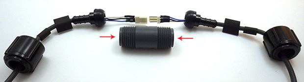
Wet-sand the ends of that nipple (arrows) with 600 & 800 grit to remove any casting seams. Smooth all o-ring seats.

On 1/2″ barbs, use a couple of sizes of heat shrink to step down (from Ø12/6 tubing) to the diameter of the cable you are using before sealing the connection with epoxy. Adhesive lined tubing helps the seal. You can also buy 1/2 NPT x 3/8 PEX adapters for thinner cables, but for some reason they cost twice as much as the larger diameter 1/2 x 1/2″ adapters (?)
As a diver, I had already seen debates about which connectors are the best on the scuba forums, and a quick Google search quickly finds many suppliers for that market. Most of these are “wet-plugable” connectors encased in delrin/rubber, and they are workhorses in many industrial and military applications. High profile companies like Seacon making a bewildering array of solutions, but their cheapest ones come in around twenty five dollars per socket, so a complete connection will set you back at least $50.

Remove the cone washer before filling with epoxy. I score the inside of these 1/2″ barbs with an old 8×125 tap to promote epoxy bonding.
Many of these commercial connectors are rated for deep ocean deployments, able to withstand thousands of psi – far more than I will subject them to in the shallow cave systems. And they often give you a short little pig-tail under the assumption that you will be using it with a cable gland , or a bulkhead connector on a nearby housing ( or at the very least a couple of layers of marine grade adhesive lined heat shrink tubing) I needed some decent cable runs so I went looking for other applications with longer lines at shallower depths . The pool & underwater lighting folks often use Bulgin electrical connectors, and the 400 series Buckaneers (rated to 10m) occasionally come up on eBay in the $10 range, But again you need to buy two sockets (male&female), and you need to buy the pins which are sold separately. So you still end up around $25 per connection.

Make sure your wires extend all the way through the nipple, or you can’t make the connection! And use soft flexible silicone wires so they fold back into the connector easily.
With all that as background, I went hunting once again through the plumbing section at the local hardware store. I reasoned that anything that could hold water in, could also hold water out, right? And I think I have come up with a solution using Nibco pex swivel adapters that is pretty cheap and can be adapted to many different applications. These plumbing adapters are rated to withstand 100 psi, which is roughly equivalent to 230 feet under water. And that is pressure from the inside out, so my gut feeling is that these things will be able to withstand slightly greater pressure in the other direction, where the forces act to increase the compression of the cone washer. The thing I like about the swivel adapter mechanism is that it applies pressure to a hard plastic lip on the other side of the washer, so as you tighten the nut there is no rotational force being applied to the parts forming the water tight seal.
These adapters come in a variety of larger & smaller diameters allowing you to use different cable thicknesses, and you can change the length of the pvc riser pipe in the middle to make more space for the internal connectors. This also gives you a way to adjust the amount of air/buoyancy along the run and with a string of connectors this might be a good way to reduce strain on the cable. I suspect that the schedule 80 tubes in the middle are the weakest point in the system, but filling the internal space with mineral oil would get these connectors to significant depth, as would a filling of paraffin wax, though that would have to be heated again to undo the joint.
Addendum

Don’t forget to smooth the seat on that male hose barb side if it has bad casting seams. You want that connection to be as clean as possible. You need to use small connectors for this M-F design.
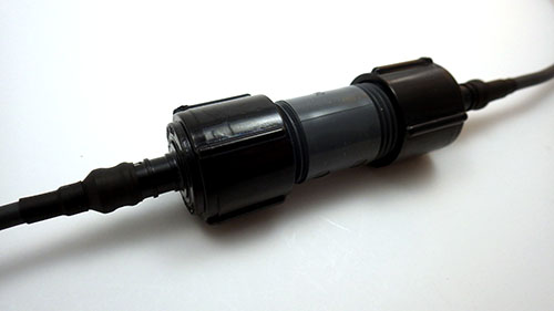
After building a few of these, I realized that it was possible to make them even simpler if the electrical connectors were small enough. In the picture here, one side has a Nibco PEX swivel adapter, while the other has a male thread NPT to PEX adapter. These are both polymer, though it is hard to find an epoxy that will bond to it with an applicator fine enough to put the adhesive into the barb cavity. These fittings are also available in brass for the same price, and the o-ring seats are much cleaner on those than the polymer adapters because there are casting seams on the plastic parts. But I don’t know how well the brass will fare in marine environments. Some of my sensors have stainless shells, so I worry about galvanic effects in salt water?

Pull these joins into the connector so they are embedded in the epoxy.
In the photo above I’ve used a three wire PC fan connector, and it “just barely” fits inside the cavity of that m/m hose barb. I will use smaller JST connectors in future, or perhaps Dean’s Micro 3pin or 4pin for something more robust. The internal diameter of the 1/2 pipe is a little over 12mm, so if you need to squeeze more connections in there you could try a couple of “mini micro” JST’s, but I find that soldering all those wires so close together is a bit irritating because it’s easy to accidentally melt the plastic, loosening the tiny pins.
I also found that the wire inside my cables were too stiff to fold neatly into this much smaller space, so I had to add some flexible 26 AWG silicone wires to the ends. After the jumpers are attached, pull the cable through so that the solder joins get embedded in the epoxy. This has the added benefit of providing a break in the insulation around the wires, so that if you do get a cut in the cable, water can’t work it’s way through the connector by wicking along the copper strands. I am still hunting for a good supplier of multi-conductor 22-24 awg cable that has a good “handling weight” for underwater applications. It’s hard to shop for something on the internet when what you are really after is something that “feels right” when you hold it in your hands.

A dual connection cap for one of our 2″ underwater housings. We now use harder PUR sheath cables because softer silicone jackets were too easily damaged during deployment dives. For a less expensive option, Luke Miller has had success using USB cables with his underwater sensors. A 3/4″ adapter from the pex connector system gives you a way to mount pressure sensors under oil.
I should add the usual provisos here about this being another of my completely experimental ideas so use this at your own risk. Pex tubing is generally rated to ~100psi (at temperatures below 74°F) and if the o-rings can withstand that then they should “theoretically” be good to about 60m depth. Translating that into the real world, I expect these connectors to be trustworthy to about 40m, which covers most of our cave deployments.
Addendum 2015-01-30
I just stumbled across a different solution to the expensive underwater connector problem. His method for waterproofing connectors using 3D printed silicone molds is beyond my current capabilities, but its nice to see it explained with such clear documentation.
Addendum 2015-02-01
If those pex adapters don’t have enough room for your cables, I found another great underwater connector project which might do the job for ya 😉
Addendum 2017-01-23

As time goes on I am reducing the number of interconnects, but even with longer chain segments I will probably stick with only 24 sensors per logger.
Just though I should add an update to mention that quite a few of these connectors have been in service for more than a year on temperature chain deployments. None of them have failed on relatively shallow deployments from 5-15m depth. The only problem I’ve had is the length of the connector itself can be challenging when you are trying to pack one of those long strings into the mesh bag for an underwater deployment.
Addendum 2018-12-05
I’ve posted a video showing how I build those underwater connectors and use them with epoxy potted sensors: ( part of our 2017 screw terminal logger series)
It’s also worth mentioning that you can improve the fit of various parts by taking advantage of the fact that they are thermoplastics:
 Rotate & heat the inside corner edge of the tube until ~ 0.5mm of the material ‘softens back’. Don’t over-do it! you don’t want to alter the tube diameter or hurt the threads. |
 Quickly press the mating o-ring onto the seat while the PVC is still soft enough to conform to the shape.
|
 Before & After heat treatment: the o-rings now form a better seal. This is faster than sanding away any rough casting seams on the parts |
Addendum 2020-04-06
These connectors & sensor mounts are part of the housing system we’ve been developing since 2015. You can see the latest underwater housing build @ DIY data-logger Housing from PVC parts

Loved reading this blog as I’m also working on a long-term datalogging project using the DS18B20.
Using this method: http://letsmakerobots.com/node/38531 I was able to quickly make a string of 10 sensors in Epoxy resin. My mold has place for 6 sensors at the same time, so two pourings will net you 12 fully enclosed sensors.
Brilliant! My own attempts to build a chain of DS18B20’s were the motivation for developing this connector system. I am just putting the finishing touches on a big post about it, and I am now digging into the more challenging issue of how to calibrate these sensors to improve their accuracy (when you don’t have a NIST pt100 available). Your casting molds are very cool, and if I had know about them before I would have tried that method to waterproof my sensors. As it is I came up with a different solution and it will be interesting to hear your feedback on it. But I am going to keep you in suspense till I get the post online 🙂
Hi Edward, awesome blog mate, in the process of having a crack at building one of your nifty little data loggers. Just a quick question on the temp sensor strings, do you think what you’ve built in this article would be suitable for monitoring soil temp at different depths on a farm?
Mark
We have been testing the temperature strings under water, and our first deployment survived for 4 months down at 10-15m. So we know they can handle the moisture side of things. But there is an important difference between that, and deploying them in the ground because the water pressure is evenly distributed around those connectors. It’s is pretty easy to imagine a rock, or some other hard object in the soil mixture applying a high point-pressure spot on the side one of those joins, producing enough warping to weaken the o-ring seals, or perhaps puncturing the heat shrink around the epoxied sensors, or the silicone jacket on the cable. So if I was deploying them under ground I would bury them very carefully, or perhaps even thread them inside of a 1/2 pipe so that they had some physical protection from these issues. Of course, then you have to deal with the pipe introducing thermal lag, etc. I am sure this has been sorted out by other earth science research groups so I would start with some literature searching at Google scholar to see how they protected their sensor strings.
First note: I’m also a caver (the dry variety), and will be shamelessly ripping off your amazing hard work here on your blog (just starting with an Arduino… I’ve got a long way to go).
My personal research is geysers (models currently), so some of the issues are similar and some are different (hey, PVC becomes about as strong as cooked spaghetti at 100 deg-C 🙂 ). I have tried making “pressure proof” electrical connections for sensors (LEGO sensors) and found that stranded connectors still had some problems. I eventually had to move to solid-copper wires embedded in marine epoxy for the pressure seals as I was getting leakage even with bare stranded wire in epoxy. Not sure if this is an issue here, but you talking about leakage within the sheath if the cable gets nicked started me thinking of it.
We are trying to bootstrap as many other research groups as possible with this project, so happy to help. There is a paper in the works so a ref would be nice when we manage to birth the thing. I’m also sitting on a huge overhaul of the codebase, which I’m planning to release when we have solid deployment data on how things like bus speed settings affect the power consumption for otherwise identical units. I’ve been cautiously waiting until I can prove that those tweaks do not compromise the reliability of the data saving process.
Leakage along the wires is one of my primary concerns, and I always either break the wires and/or at least plug up the splice connections with solder in the epoxy to localize the damage it would cause. Once the water hits one of the nodes, I am pretty sure it would be stopped.
I hear you about the PVC softening, in fact I was heat-gunning pipe into flat stock for some of the early prototypes. But even at regular temperatures the irrigation risers in the middle will fail once we get down to more serious depth, so I have already been looking into building these connectors with brass/bronze fittings to withstand considerably more pressure:
http://www.menards.com/main/plumbing/rough-plumbing/pipe-tubing-hoses-fittings-accessories/shop-all-pipe-fittings/pex-pipe-fittings-tools/nibco-pex-female-thread-swivel-adapter/p-1444449332562-c-9381.htm?tid=-3021794490574292097
Those will take the heat without turning into noodles. You would still have to do your homework on those cone washers, as I suspect they use garden variety EPDM, and you probably would have to source a more heat resistant compound. And it will take more work tapping them to aid the internal epoxy bond. If you go this route I think everyone would love to hear about your results, especially wrt choosing a good epoxy for that temp. range and how you deal with the attendant thermal expansion issue.
I’d also love to hear what cable sheathing you use: Silicone is great for flexiblity & temp but it’s soft as heck, while the harder polyurethane jacket cables coil up on us because they retain too much inherent curvature under water. So we are still searching for the ‘perfect’ solution there.
I’ve not tried deployments *into* active thermal systems yet, because they are (a) hard to get to (rarer than caves), and (b) carefully protected (the NPS does *not* casually allow you to deploy anything in or about a geyser basin). So so far, I’ve not had that problem.
But the models I build are made out of cheap materials; like you I wanted to do this on less than a professional research budget. PVC pipe is easy to work with, and inexpensive… but does loose 90% of its structural stability at 100° C. That resulted in… some very “interesting” failures on my driveway (did you know that several gallons of boiling water will not only kill grass, but sterilize the soil for a couple years?).
I’ve made my own odd PVC fittings, with a Dremel and PVC solvent you can do things like weld half a compression repair fitting (CPVC for thermal stability) into the side of a model, providing an instant instrument port. I’ve used temperature sensors there (inserted through rubber bottle stoppers that fit the compression fitting), as well as ported pressure sensors… but I doubt I can expose a 24-bit ADC pressure sensor directly to boiling water (temperature compensation only goes so far), so I’ll have to port those (I’ve got ideas). These compression fittings are also handy in putting in windows (I shine a laser through onto a phototransistor to detect bubbles).
For logging the model geyser systems, power isn’t an issue – but mm water depth resolution is, as well as good temperature measurements, which if why I ended up on your excellent blog (you’re even telling me how to calibrate? Thank you!!). but the plumbing and pressure-proofing aspect is also useful, and you got me re-interested in logging in actual caves (so for that… I get to learn the low-power stuff). Trying to come up with an airflow meter on the cheap for in-cave deployment is sort of an interesting challenge… for man-made entrances it’s much easier (you *want* to keep those sealed, so a device that obstructs airflow is fine) but it’s going to be a lot bought in open cave passages (where I need to measure small air currents, but not interfere with existing airflow).
WRT air flow: Ive been keeping a close eye on the DIY anemometer projects. Those are still still at the high end of what I think I could tackle, and my wifes wish list is already so long that I have not mentioned the anemometers to her yet. But I think they offer some real potential for cave researchers if they can resolve down to the sub m/second range. Often our air flows are so slow that we have to resort to the ‘smoke puff and meter sticks’ method to estimate air velocities.
WRT: pressure: I am sure there are some industrial pressure sensors that would be far more robust than the MS5803’s I’m using. Some of them use weird bus/protocols but I’m sure you will find someone making it work with an Arduino somewhere. Or perhaps you could buffer the cheaper sensors inside of a reservoir of mineral oil, for a short term cooling solution using simple thermal mass?
WRT: calibration: Thanks! I think of my projects at roughly 1/3 building, 1/3 coding, and 1/3 calibration. And the ‘experts’ always suggest methods that rely on $2-10K pieces of equipment to accomplish. Robust calibration procedures (that a regular person can do on the kitchen table without spending NSF grant level money) are what the makers movement needs to have a real impact in the sciences.
And….the comment about the failed experiment on the driveway made my day, as there have been plenty of ‘reminder marks’ on the house at this end 🙂
Dear Ed, Would you add a more descriptive parts list for your underwater connectors? Thank you. Your project is really interesting.
Hi Diana,
The ones I am currently using to make the connectors are:
1x NIBCO 1/2″ PEX Faucet Poly Swivel Adapter $2.18 per 2pack
1x Rain Bird 1/2″ x 2″ PVC RISER $1.79 each
1x #1241 Deans Micro 4B connector $1.50 each
You can use longer riser tubes to add more buoyancy to your cables if you need it. I find I have to wet sand (800grit) casting spurs from one end of the riser pipe for a good seal. Use some heat shrink to step down from the pex size to whatever diameter cable you are using in order to provide a plug when you pour the epoxy into the center pipe. I tap the inside of the swivel adapter to make the epoxy bond stronger. My taping set came in a box of parts from a garage sale, and the size on the thread is listed as 8/125, but I have no idea what that actually means. The 4-pin deans connector just barely fits inside the 1/2″ riser pipe, and you could use whatever other connector type you wanted, provided it fits. There are 2 & 3 pin options that fit more easily.
Epoxy is Loctite e30-cl, with this applicator gun and MA6.3-21S Static Mixer Nozzles.
Other diameter sizes are linked in the post, and there are oodles of different brands/parts that would work if you can’t find the specific ones I’ve listed above at your local hardware store. I use Adafuit’s 26AWG silicone wire inside the PEX connectors, as it is extremely flexible, and you always want a solder joint inside the epoxy so that there is no continuous path for water to creep along if you get a cut on your wire insulation.
Thank you so much, and for responding so quickly!! I am an engineering student, and member of a group of students that are building an ROV. We are, of course, always looking for less expensive ways to waterproof our connectors and such. Thank you for your immediate and descriptive response!! It’s enormously helpful.
If you are building an ROV be sure to check out the many ROV forums like HombuiltROV with questions about tethers. My current favorite multi strand/multi wire cable is the four conductor M12C from Omega, but the question of jacketing is tough. The silicone jacket cables are beautifully flexible under water, but then the sheath is easily damaged. The PUR jacket cables are almost bullet proof, but they retain enough coil to snag at every opportunity. If you find another good source of cabling for underwater work, I would REALLY like to hear about your experiences with it.
We have only deployed our connectors down to 30m depth, but the pressure rating on the fittings themselves is much higher than that. Also look at the way I encapsulate the DS18b20 temp sensors in epoxy, as you might use that method to connect lengths of cable together (I’ve also used it to repair broken cables…).
What three and four strand cable have you found to use with this set-up? Using the silicone-based flexible wires inside the couplings I understand… but the black-sheather cable your using here is what I’m curious about.
Dang, every time I come back here I’ve got so much more to catch up on 🙂
I’ve been using silicone and pur jacket cables from http://www.omega.com. They have a set of extension cables for their line of RTD sensors, but they are pretty expensive since they come with connector end attached (which I just cut off). The silicone jacket cables handle beautifully under water, but they also break quickly from flexing because they are only 7-conductor. The pur jacket cables are have higher strand count, but the stiffness of the pur outer jacket also makes them much harder to work with for the kind of multi sensor arrangements I’m trying to build. I really need to go hunting for high strand count (say 20-30 strands) silicone jacket cables by the roll, but I just have not had time for that yet.
Update on cheap cables, especially for your educational friends… I have way too many old USB cables cluttering up my home (and probably a lot of Goodwill stores). Hey, what do you know, four-stranded jacketed cable just laying about waiting to be re-used :). No idea yet how they’ll survive “in the wild”, but for in classroom experiments they would seem to be ideal.
That’s a brilliant idea! I expect the resistance/capacitance specs will vary quite a bit, but will do some tests & post results when I get time. Curious how easy those cables would be to splice into for multi-drop sensors? I guess it all depends on the jacket material.